- PDF
Workflow Manager Usage Guidelines
- PDF
Article Overview
The following article describes guidelines for using the Workflow Manager.
Adding Building Blocks to the Work Area
(See Figure 1)
Building blocks are added to the work area by drag and drop. After a building block is placed in the work area, its properties appear on the left (1) and it displays additional buttons:
- Delete
 (2)
(2) - Open
 (3) - enables you to open a specific area in the Builder platform, such as the Webflow
 - Copy
 (4)
(4)
A building block with an empty required property will display a red frame (5).
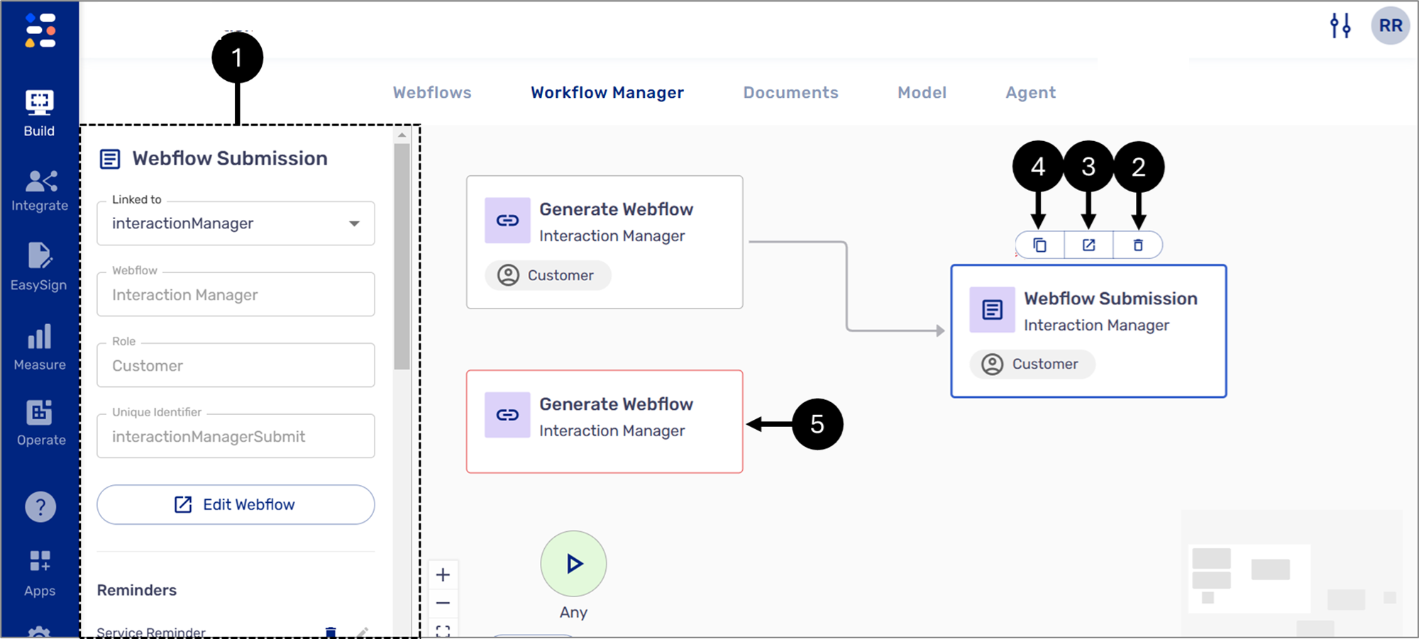
Figure 1: Adding to the Work Area
Connecting Building Blocks
(See Figure 3 to Figure 5)
To map a process and create detailed visualizations to understand the relationship between building blocks better, we need to establish connections. Each building block has at least one connection point (1), for example:
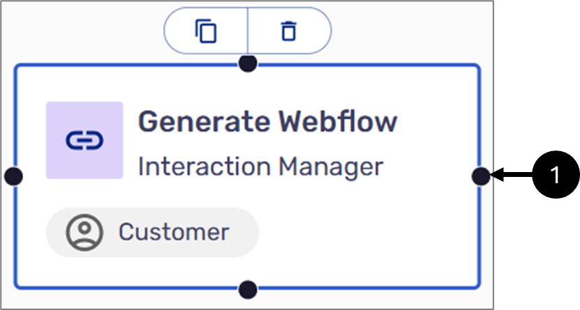
Figure 3: Building Block Connecting Points
Hover over a connection point and wait for the icon to appear to establish a connection between building blocks. Then, with the left click, pull a connecting line toward the next building block and attach it to a connection point.

Figure 4: Connected Building Blocks
When multiple building blocks branch out from the same flow and later connect to a single following building block, that block will not initiate until all connected building blocks are fulfilled. For example, in the flow shown in Figure 5, submitting the Webflow triggers both an integration and an email to the customer representative. The customer thank-you email will only be sent after both the integration has been initiated and the customer representative email has been sent.
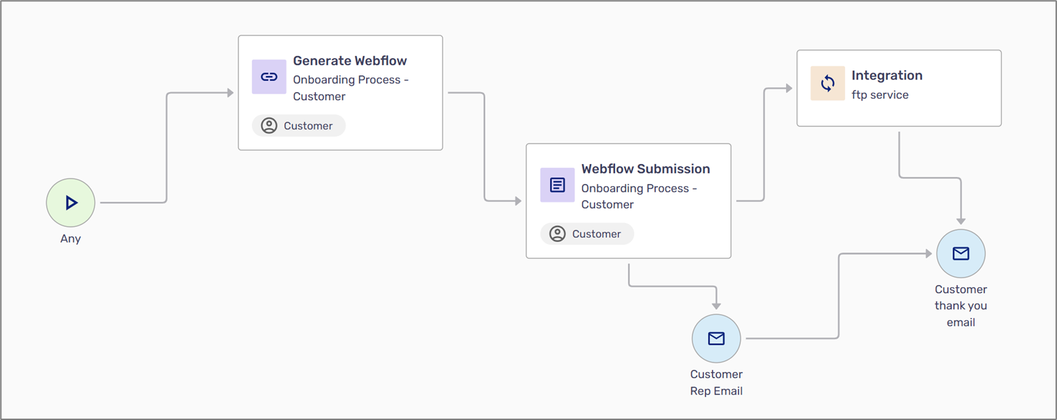
Figure 5: Branched Out Building Blocks
Arrow Direction and Data Flow
(See Figure 6 and Figure 7)
When connecting building blocks, the direction of the arrows signifies the flow of data between them. Using the wrong direction can cause errors and prevent data from being auto-filled or processed correctly. In the following example, the data flow starts with the Generate Webflow building block to the Webflow Submission building block. This is the accurate way to connect the two building blocks. When clicking the Webflow Submission building block to display its properties, the Linked to and Role properties are automatically filled.
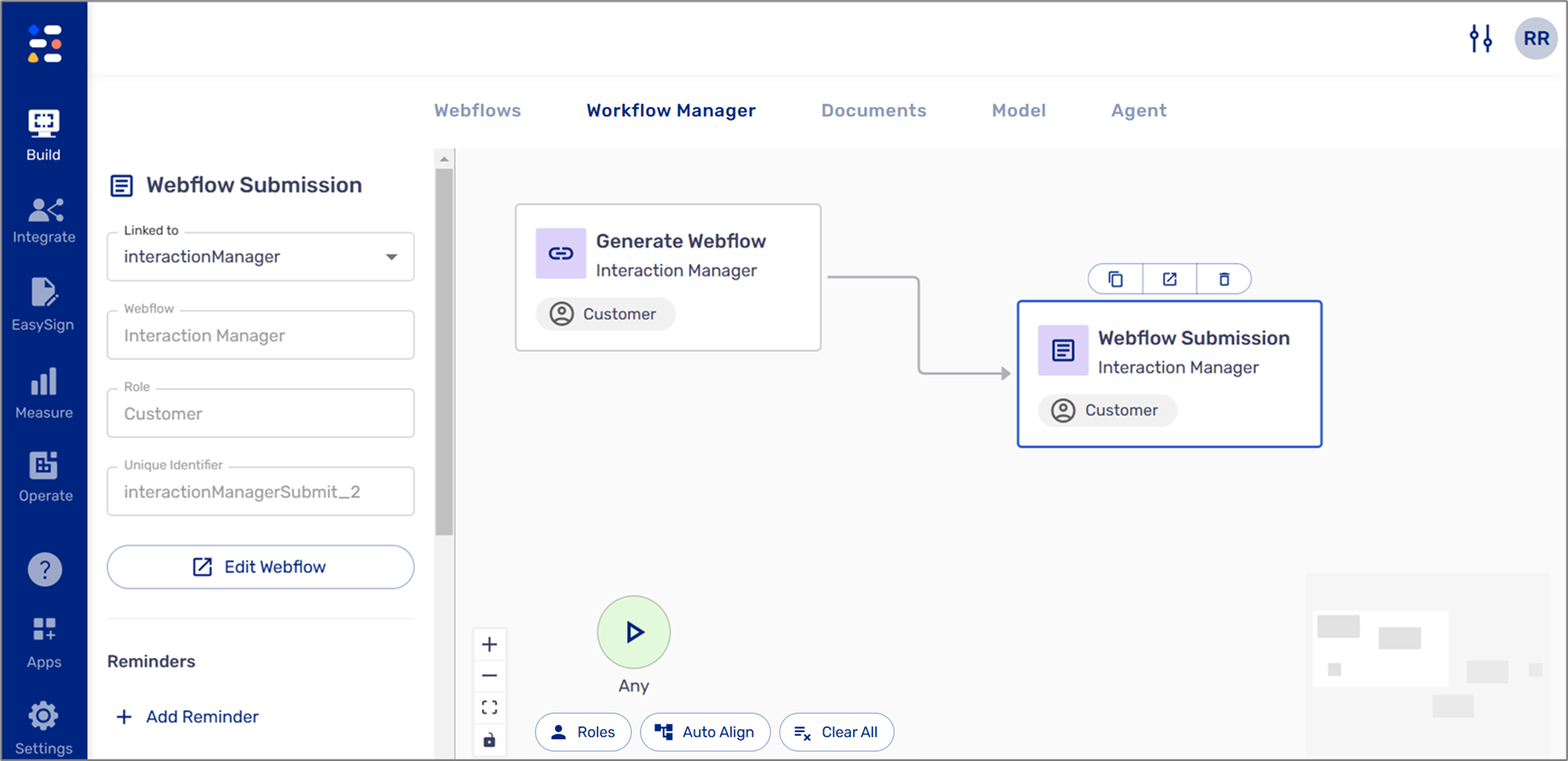
Figure 6: Connected Building Blocks and Data Flow 1 of 2
The wrong way to connect the two building blocks is to connect them from the Webflow Submission to the Generate Webflow.
This will cause the Webflow Submission properties to remain empty and display an error indication (red frame) around the Webflow Submission building block.
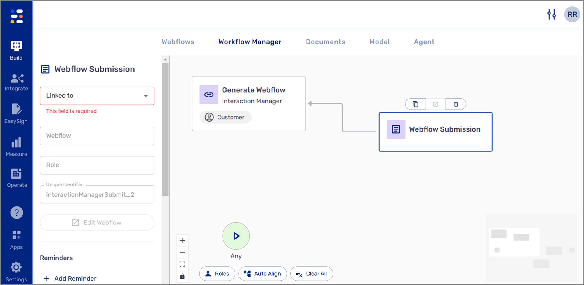
Figure 7: Connected Building Blocks and Data Flow 2 of 2
Starting Points
(See Figure 8)
Initially, every Workflow Manager appears with one default Any Start Building block. The Any start is the default entry point for handling initiations from a source not explicitly defined in the workflow. Every process must begin with Any or with other Start building blocks located under the Business Logic category. A process can have more than one Start building block.
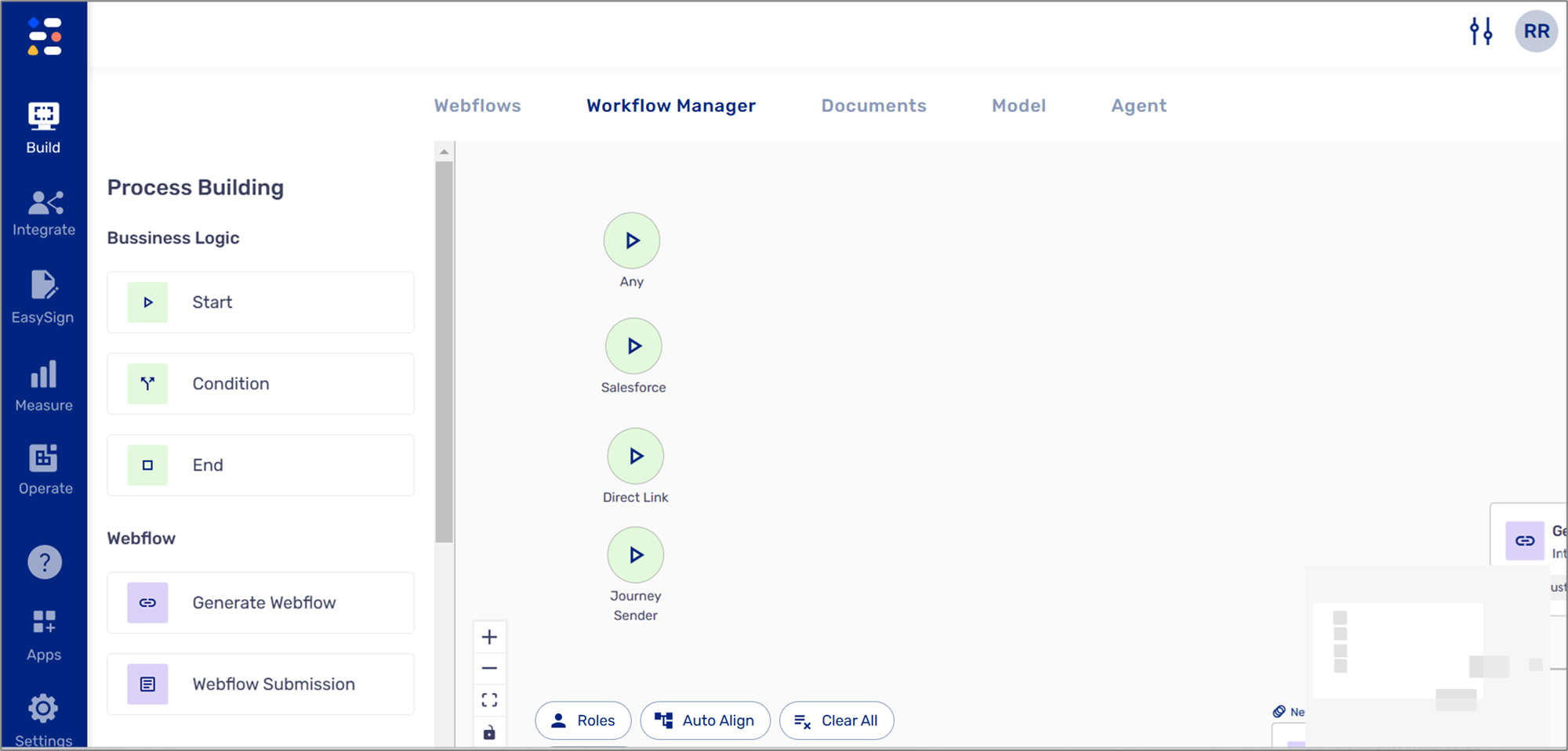
Figure 8: Start Building Block
Example 1
(See Figure 9)
The following example describes the flow of a process that is initiated from a portal:
- A Portal contains a link to a digital process
- The end-user accesses a portal and clicks a link to open a digital process
- Direct Link -> Generate Webflow -> Webflow Submission
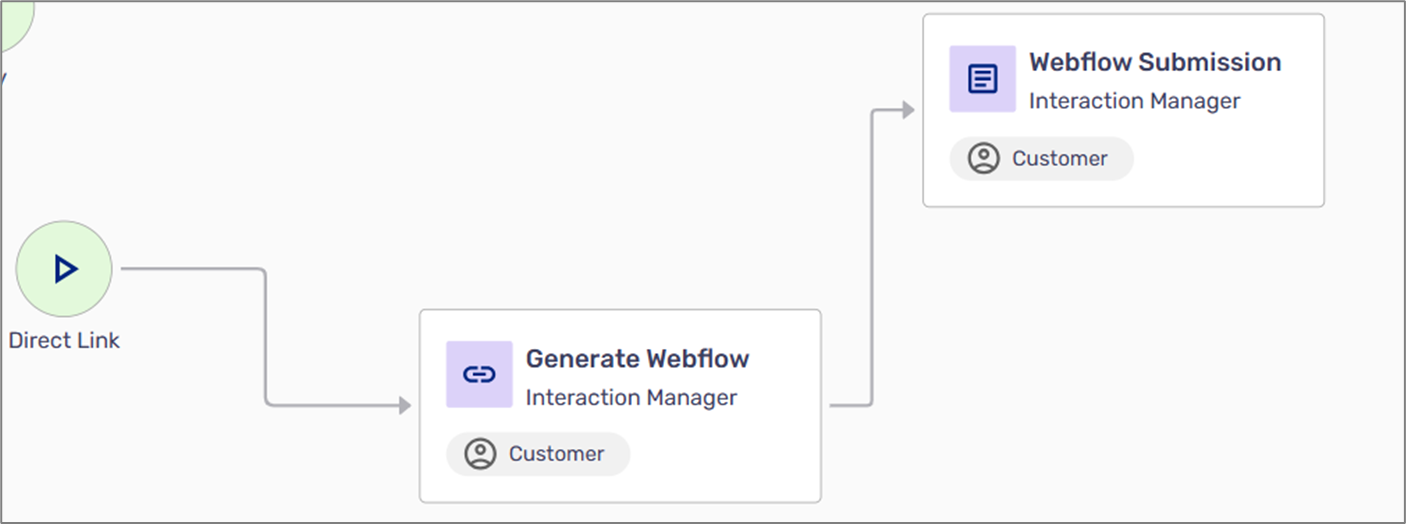
Figure 9: Workflow Example 1
Example 2
(See Figure 10)
The following example describes the flow of a process that is initiated from a CRM system like Salesforce:
- An agent accesses Salesforce
- Inside Salesforce, the agent displays a list of EasySend processes
- The agent generates a new process link
- The link is sent via email
- The end-user clicks the link in the email to access the process
- Salesforce -> Integration -> Generate Webflow -> Email -> Webflow Submission
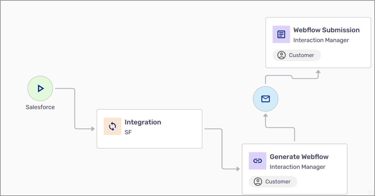
Figure 10: Workflow Example 2
Example 3
(See Figure 11)
The following example describes the flow of a process that is initiated using the Journey Sender:
- An agent is sending a link to a process using the Journey Sender
- An end-user receives the link via email
- The end-user clicks the link to access the process
- Journey Sender -> Generate Webflow -> Email ->Webflow Submission
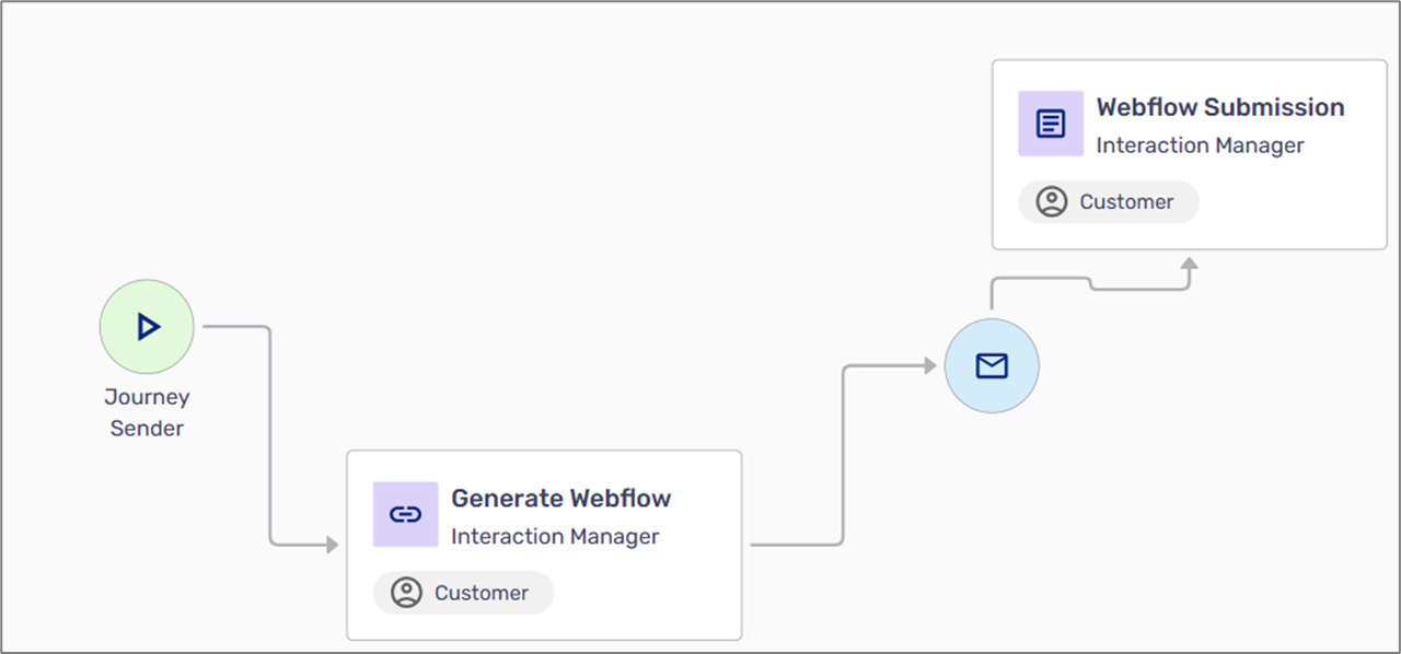
Figure 11: Workflow Example 3
Example 4
(See Figure 12)
The following example describes the flow of a process that is initiated from an API:
- A link to a process is generated using an API
- An email is sent to the end-user
- The end-user clicks the link in the email to access the process
- API -> Integration -> Generate Webflow -> Email -> Webflow Submission

Figure 12: Workflow Example 4
Creating Conditions
(See Figure 13)
Use a condition to split the workflow of the process into different paths, for example, a process will either end or continue if a spouse needs to be involved.

Figure 13: Using a Condition
Using Integrations
(See Figure 14)
Use the Integration building block to describe where to send data at each stage of the process, for example:
- When the agent sends a link of the process through a CRM system to the end-user, it is prefilled with data
- When the end-user submits the process, new information is integrated back into the CRM
- When the end-user submits the process, all uploaded files are sent to an FTP by using Webhooks
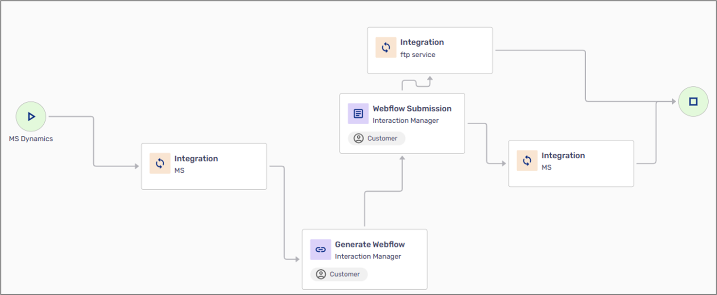
Figure 14: Using Integrations
Using Co-Browsing
(See Figure 15 to Figure 19)
The Co-Browsing Link switch allows other end-users, such as your agents, to join the customer's process with a co-browsing link and provide real-time online assistance. To generate a Co-Browsing link, perform the following steps:
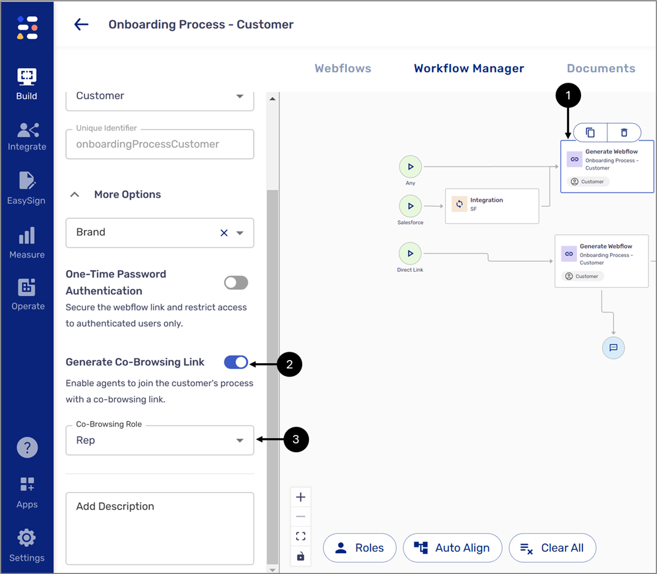
Figure 15: Using Co-Browsing 1 of 5
- Click the desired Generate Webflow building block (1).
- Toggle the Generate Co-Browsing Link switch to on (2).
- Set the desired Co-Browsing Role (3).
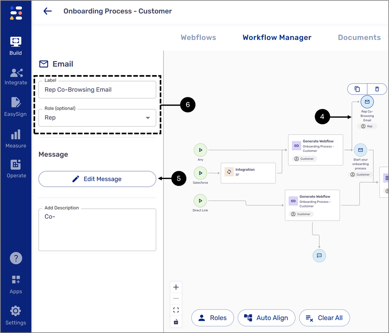
Figure 16: Using Co-Browsing 2 of 5
- Drag and drop an Email Building block and connect the Generate Webflow Building Block to it - Generate Webflow -> Email (4).
- Edit the Email properties (5).
- Click the Edit Message button (6).
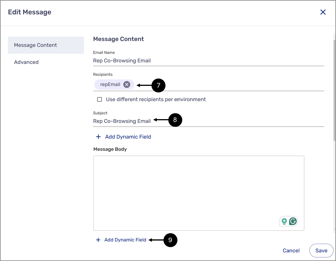
Figure 17: Using Co-Browsing 3 of 5
- Add the recipient (7).
- Add the subject (8).
- Click the + Add Dynamic Field option (9).
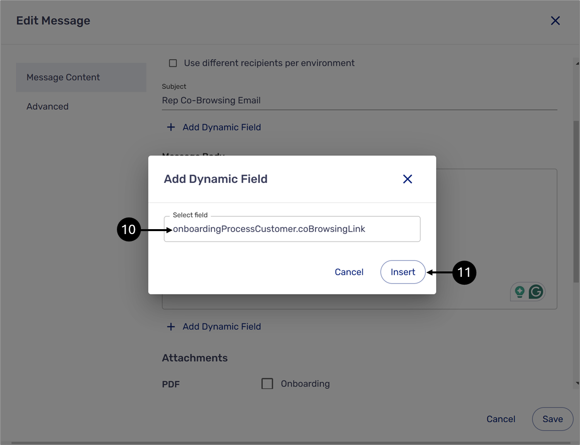
Figure 18: Using Co-Browsing 4 of 5
- Scroll and add the coBrowsingLink (10).
- Click the Insert button (11).
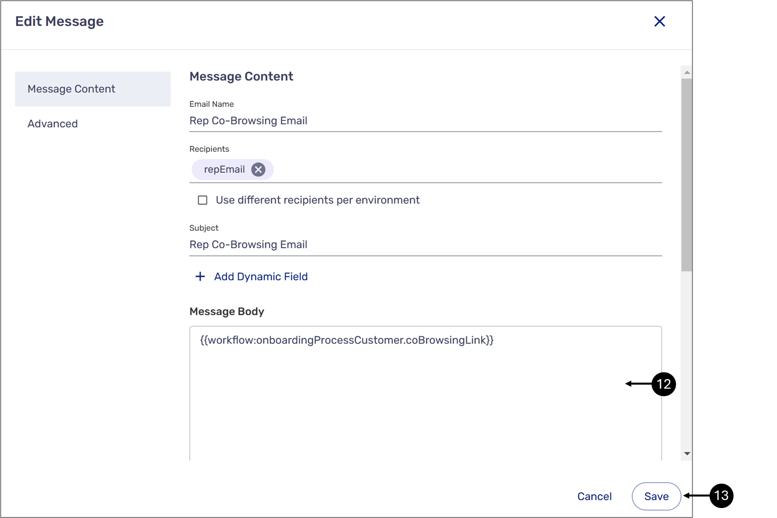
Figure 19: Using Co-Browsing 5 of 5
- Add additional text to the message body if required (12).
- Click the Save button (13).
Adding Process Links
The following sections describe different scenarios for adding process links.
Process With One Webflow
(See Figure 20 to Figure 23)
If your flow branches out using the same Webflow, each instance will have a unique identifier, which can be used when adding links. For example, in the following flow, a customer starts an onboarding process. According to the condition, if a spouse is involved, they will need a link to the process that will be sent via email.
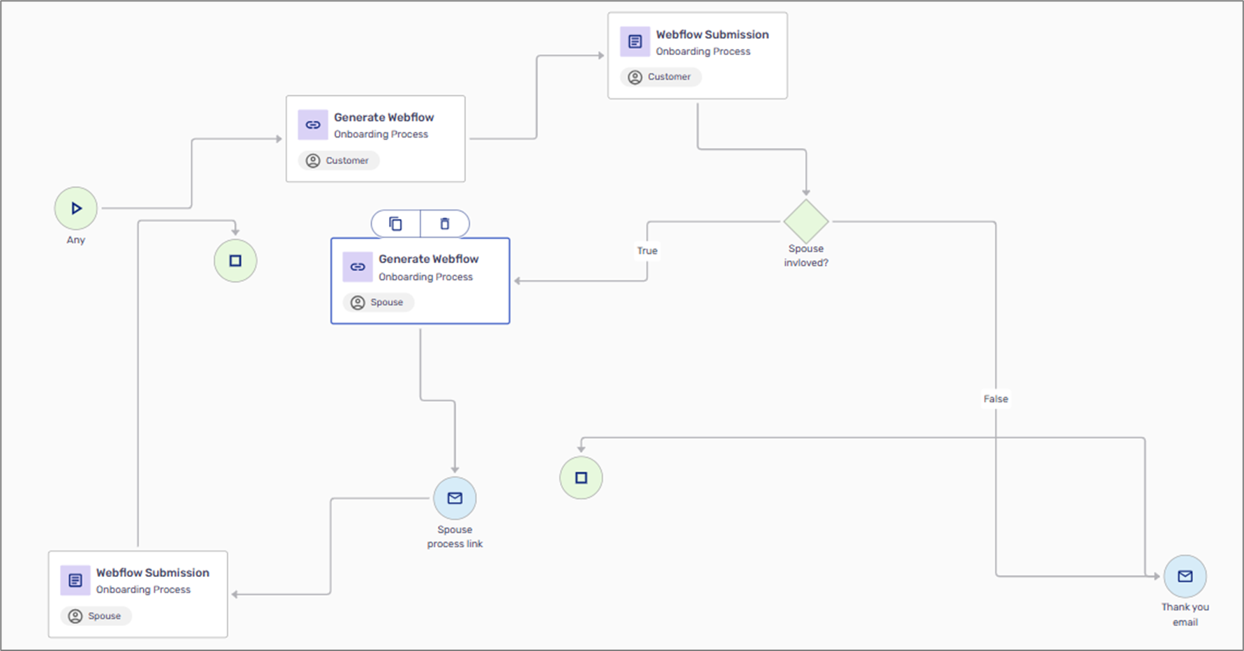
Figure 20: Simple Flow
The flow contains two Generate Webflow building blocks, the first one generates a link for the customer, and the second one generates a link for the spouse and sends it via email. Each Generate Webflow building block has a unique identifier:
- The first Generate Webflow - onboardingProcess
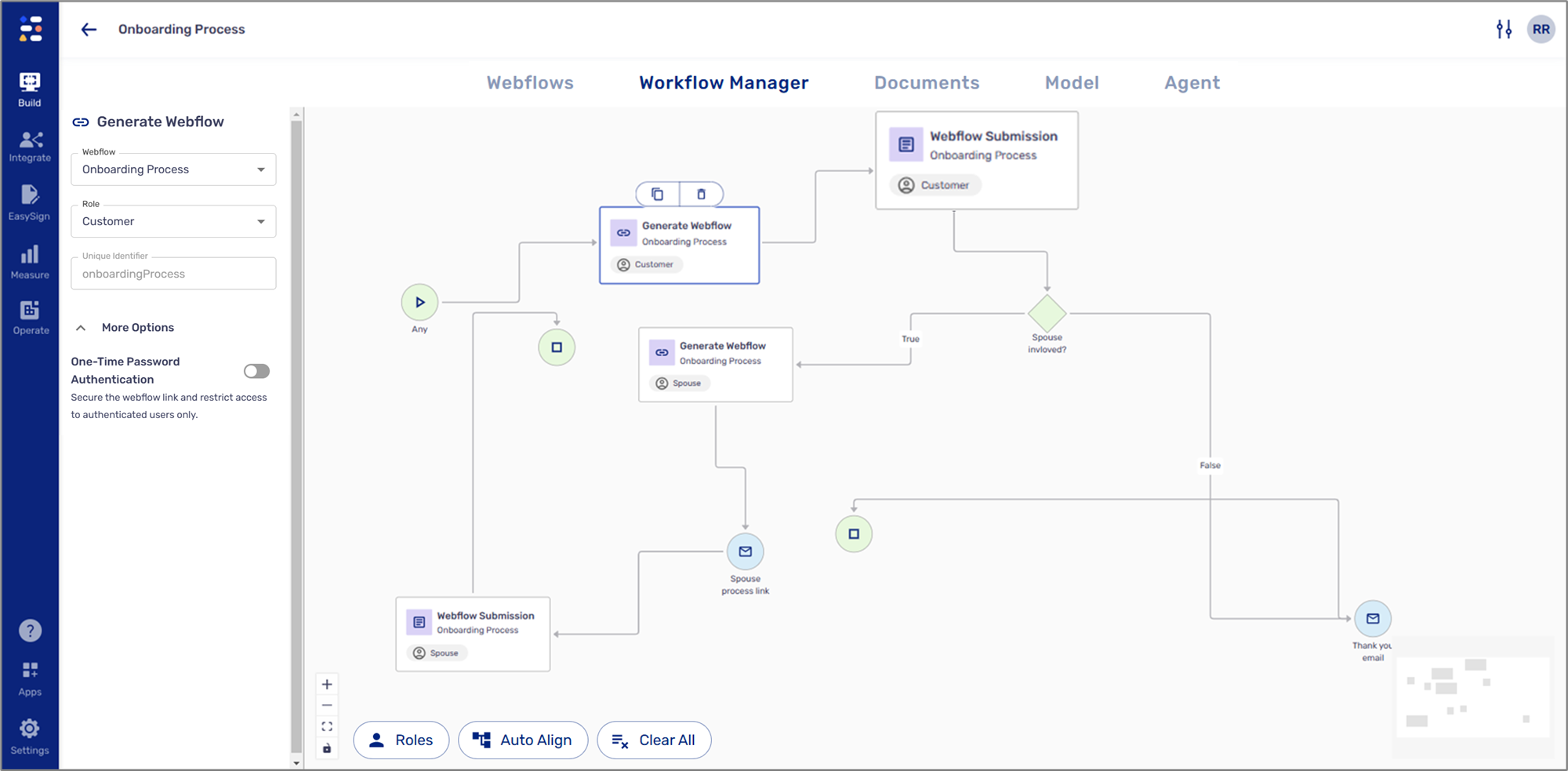
Figure 21: First Generate Webflow
- The second Generate Webflow - onboardingProcess_1
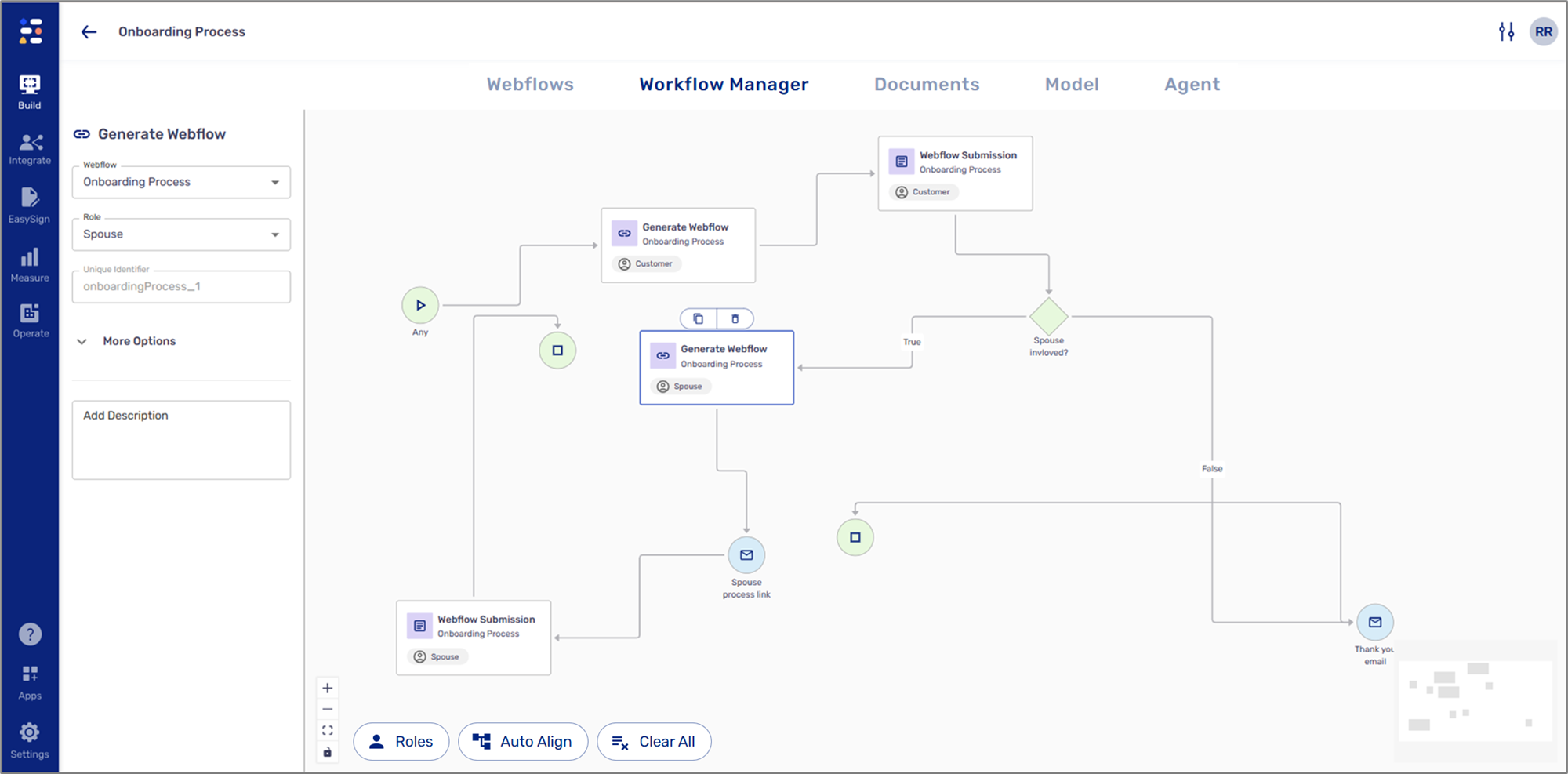
Figure 22: Second Generate Webflow
When editing the email for the spouse's link (labeled 'Spouse Process Link'), ensure that the added process link comes from the second Generate Webflow building block, which is directly connected to the email.
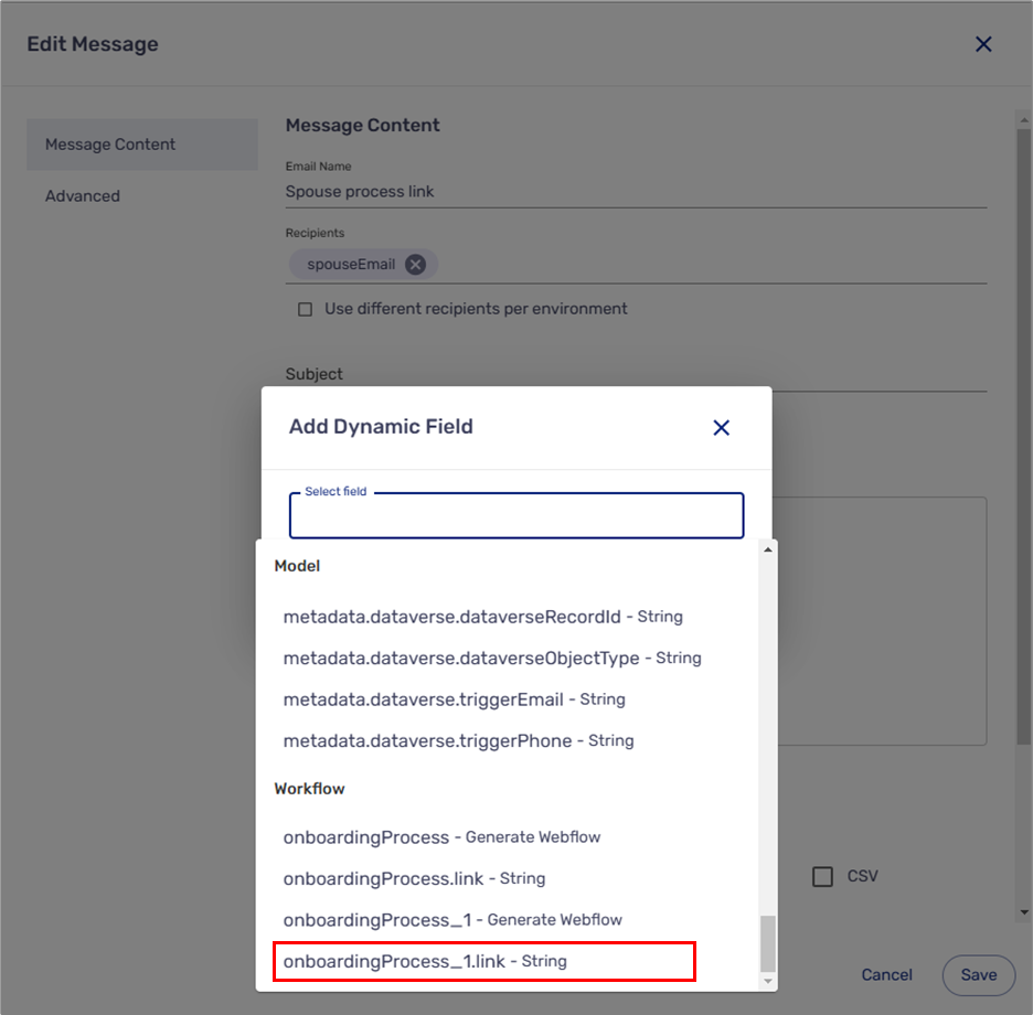
Figure 23: Adding Process Link
Process With Multiple Webflows
(See Figure 24 and Figure 25)
If your process includes two different Webflows, add the link according to the Webflow that is connected to the email. For example, in the following flow, a customer starts an onboarding process with one Webflow. According to the condition, if a spouse is involved, they will need a link to a second Webflow that will be sent via email.
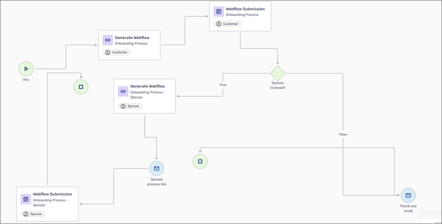
Figure 24: Flow With Two Webflows
When editing the email for the spouse's link (labeled 'Spouse Process Link'), ensure that the added process link is for the second Webflow.
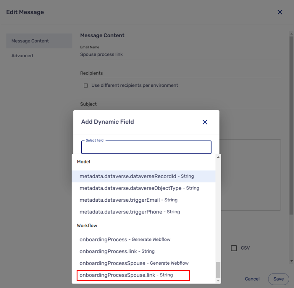
Figure 25: Adding Second Webflow Link
Additional Guidelines
- Before using the Workflow Manager, perform a specification process as described in the Specification Process article
- If required, add additional Webflows
- Create roles
- Use the Workflow Manager to map and visualize your process according to the specification process
- Configure the properties of each building block
- Build your process, business logic, and services
- Go back to the Workflow Manager and configure the workflow:
- Communication channels + reminders (emails and SMS)
- Authentication
- Conditions
- Services

