Article Overview
The following article describes EasySend's File Storage Server - resource, and integration step.
File Storage Server
A file storage server is responsible for the storage and management of data files. It enables users to share information over a network without having to physically transfer files. Using EasySend's platform, files that were uploaded while using a digital process can be sent to different locations using different protocols by creating resources and integrations.
Navigating to the Services Screen
(See Figure 1 and Figure 2)
Integrations and resources in your environment can be created using the Integrate tab (1) and the Services screen (2).
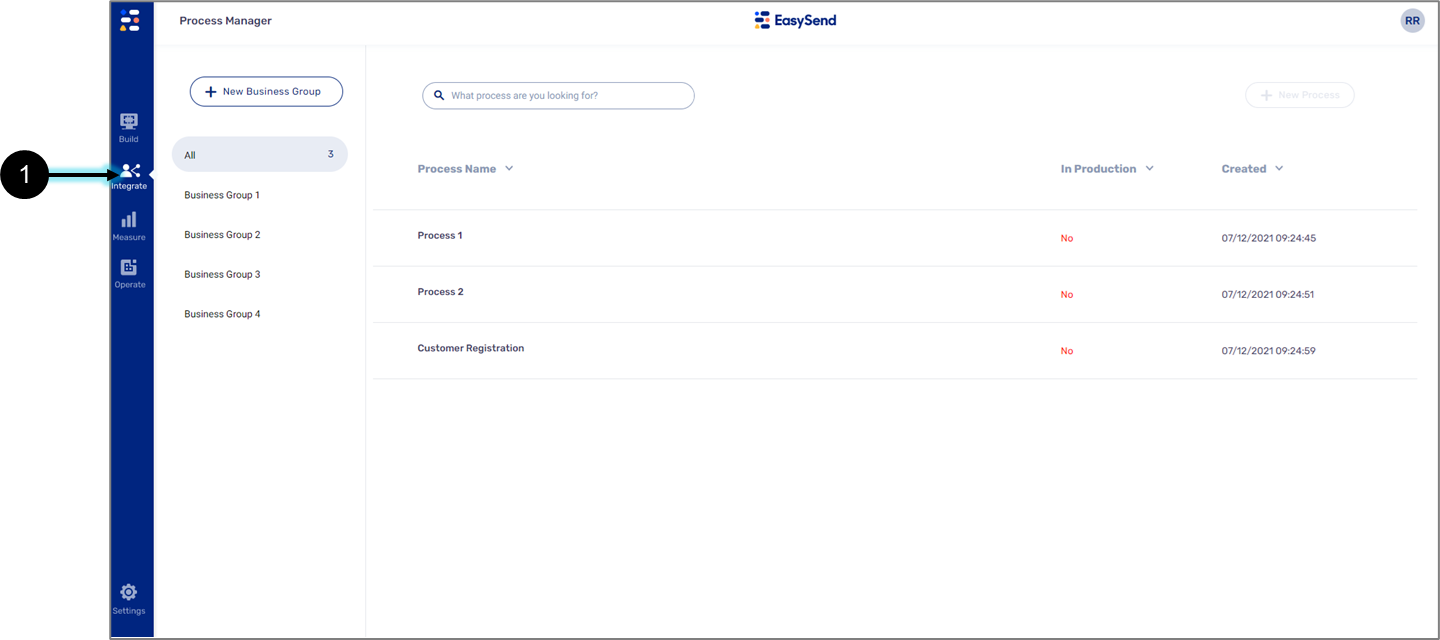
Figure 1: Integrate Tab
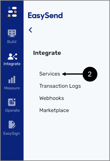
Figure 2: Services
Creating a File Storage Server Resource
(See Figure 3 and Figure 4)
Once inside the Services screen, a new File Storage Server resource can be created by clicking the Resources tab (1) and then the File Storage Server option (2).
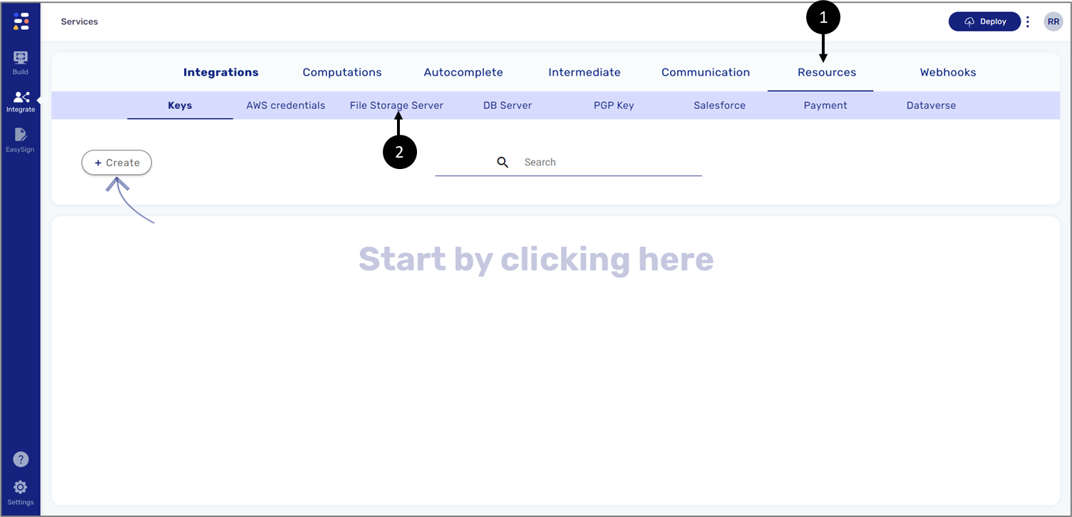
Figure 3: Resources -> File Storage Server
Clicking + Create (3) will open the File Storage Server window.
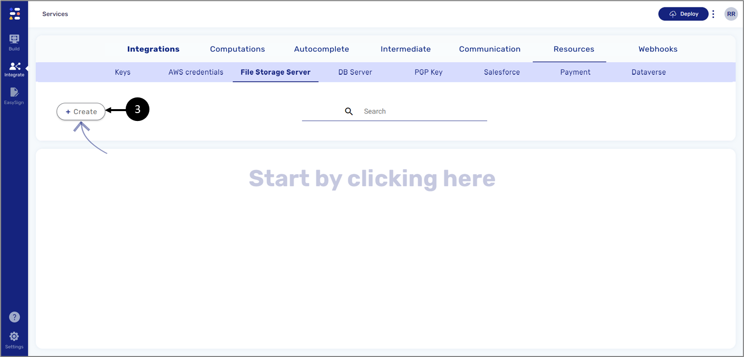
Figure 4: + Create Button
File Storage Server Window
(See Figure 5 and Figure 6)
The File Storage Server window is used for configuring the resource. First, we provide a name (1), and then we select the Server type (2). The content that the window displays varies according to the selected server type.
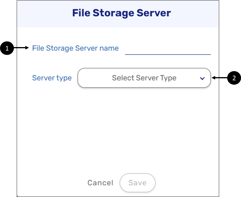
Figure 5: File Storage Server Window
The server types are:
- S3
- Local Disk
- File Transfer Protocol (FTP)
- Secure File Transfer Protocol (SFTP)
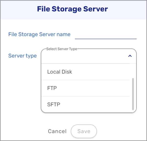
Figure 6: Server Type List
Server Type S3
(See Figure 7 and Figure 8)
Amazon S3 (Simple Storage Service) is a service offered by Amazon Web Services (AWS) that provides object storage through a web service interface. Using this server type, the following information must be provided:
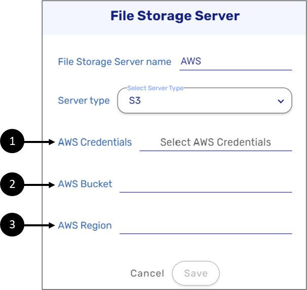
Figure 7: File Storage Server - S3
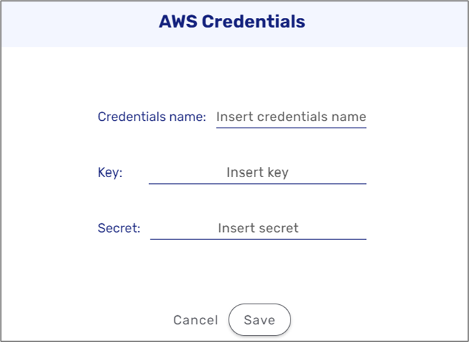
- AWS Credentials (1) - the credentials are created as a separate resource. If the credentials already exist in the environment, they can be selected (4), and if not, they can be created either by using the File Storage Server window (5).
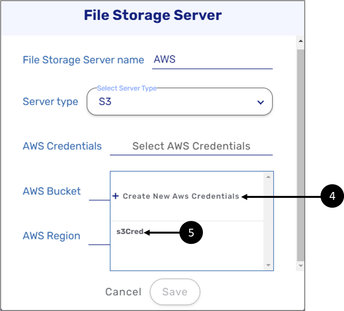
Figure 8: AWS Credentials
- Name
- Key
- Secret
- AWS Bucket (2) - an Amazon S3 bucket is a public cloud storage resource available in the AWS S3 platform. It provides object-based storage, where data is stored inside S3 buckets in distinct units called objects instead of files. Amazon S3 buckets are similar to file folders and can be used to store, retrieve, back up, and access objects. Each object has three main components:
- The object's content or data
- A unique identifier for the object
- Descriptive metadata, including the object's name, URL, and size
- AWS Region - AWS Cloud computing resources are housed in highly available data center facilities. To provide additional scalability and reliability, these data center facilities are located in different physical locations. These locations are categorized by regions and Availability Zones. AWS Regions are large and widely dispersed into separate geographic locations. Availability Zones are distinct locations within an AWS Region that are engineered to be isolated from failures in other Availability Zones. They provide inexpensive, low-latency network connectivity to other Availability Zones in the same AWS Region.
Server Type Local Disk
(See Figure 9)
This type of file storage is compatible with organizations that work with software, computers, and servers that are installed on-premises (on-prem), rather than at a remote facility such as a server farm or cloud. Using this server type, information about a local disk path (1) must be provided.
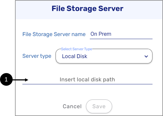
Figure 9: File Storage Server - Local Disk
Server Type File Transfer Protocol (FTP)
(See Figure 10)
FTP is a standard communication protocol used for the transfer of computer files from a server to a client on a computer network. FTP users authenticate themselves with a clear-text sign-in protocol, normally in the form of a username and password. For secure transmission that protects the username and password, and encrypts the content, FTP is often secured with Transport Layer Security (TLS) or FTP Secure (FTPS). Using this server type the following information must be provided:
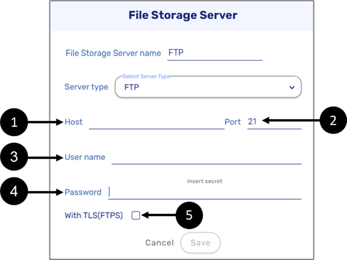
Figure 10: File Storage Server - Local Disk
- Host (1)
- Port (2) - 21 by default
- User name (3)
- Password (4)
- Enable/disable TLS(FTPS)
Server Type Secure File Transfer Protocol (SFTP)
(See Figure 11 and Figure 12)
SFTP is a secure file transfer protocol that uses secure shell encryption to provide a high level of security for sending and receiving file transfers.
SFTP is similar to FTPS in that it uses Advanced Encryption Standard (AES) and other algorithms to secure data as it travels between different systems. SFTP also provides several methods to fulfill the authentication of a connection, such as user IDs and passwords, Secure Shell (SSH) keys, or combinations of these. Using the server type, the following information must be provided:
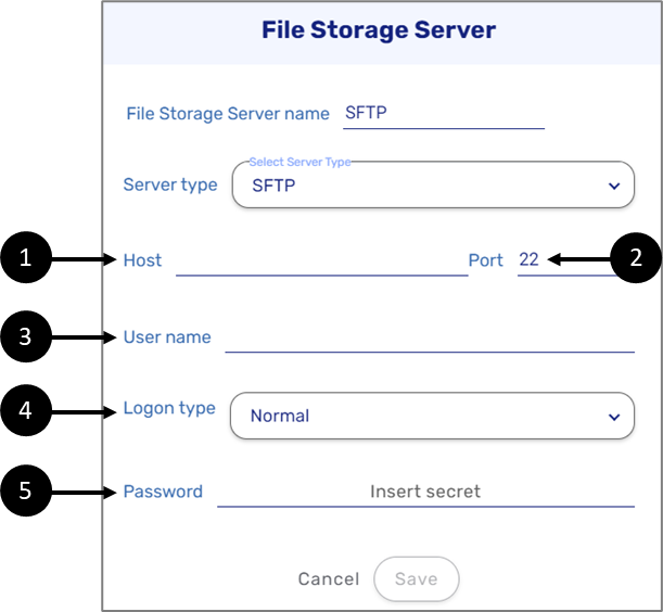
Figure 11: File Storage Server - SFTP
- Host (1)
- Port (2) - 22 by default
- User name (3)
- Logon type (4) - three options:
- Normal - User name and Password are required
- Key file password protected - User name and Secure Shell (SSH) Key file are required
- Key file login password - User name, Password, and SSH Key file are required
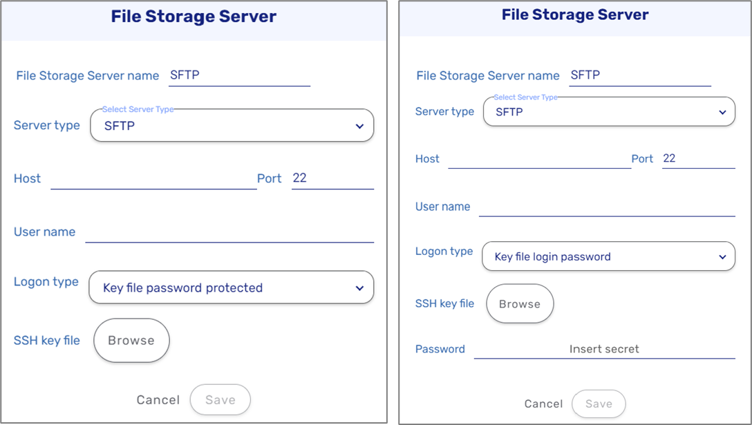
Figure 12: File Storage Server - SFTP
- Password (5)
Creating an Integration
(See Figure 13 and Figure 14)
After creating a resource, we will use it as a step in an integration. To create a new integration, click the Integrations tab (1) and then the + Create button (2).
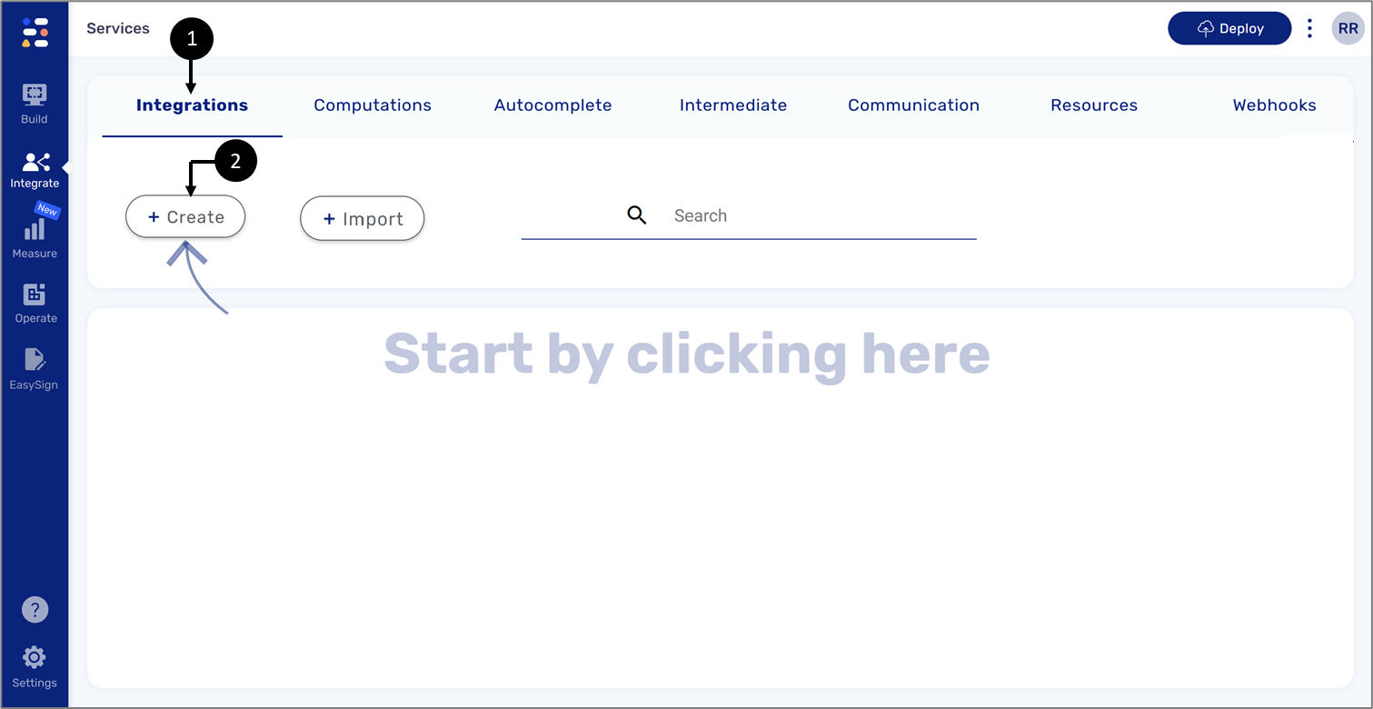
Figure 13: Creating an Integration
When creating an integration, four sections appear:
- Service name (1) - this section is used for providing a name for the integration. If no name is provided, the integration will appear as un-named.
- Inputs (2)
- Different steps (3)
- Outputs (4)
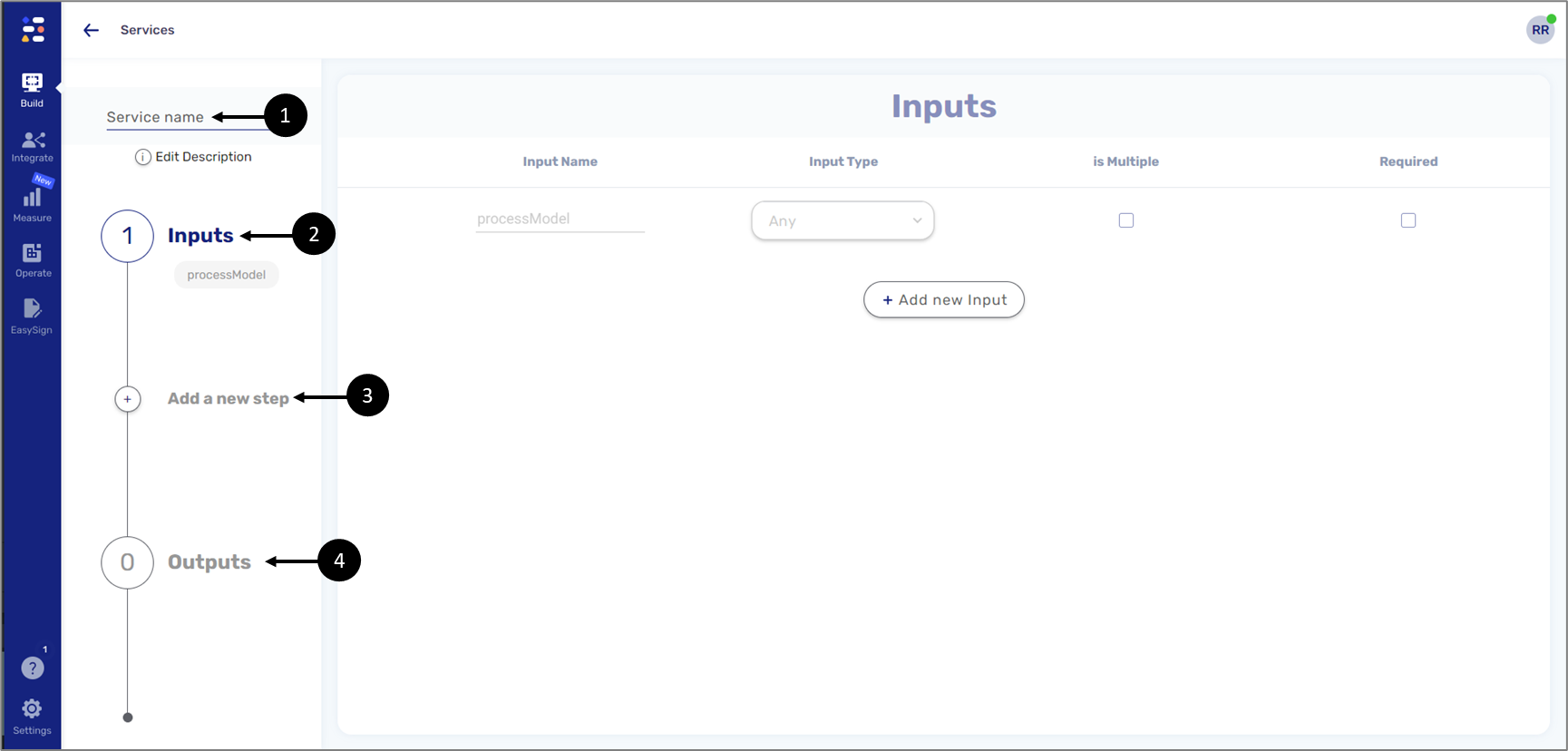
Figure 14: Integration Sections
File Storage Integration Structure
The following sections describe the structure of a file storage integration.
Inputs
(See Figure 15)
By default, an integration contains the processModel input (1). This default value indicates that the input information will come from the Model, regardless of the process that is using the integration. Additional inputs are added by clicking the +Add new Input button (2).
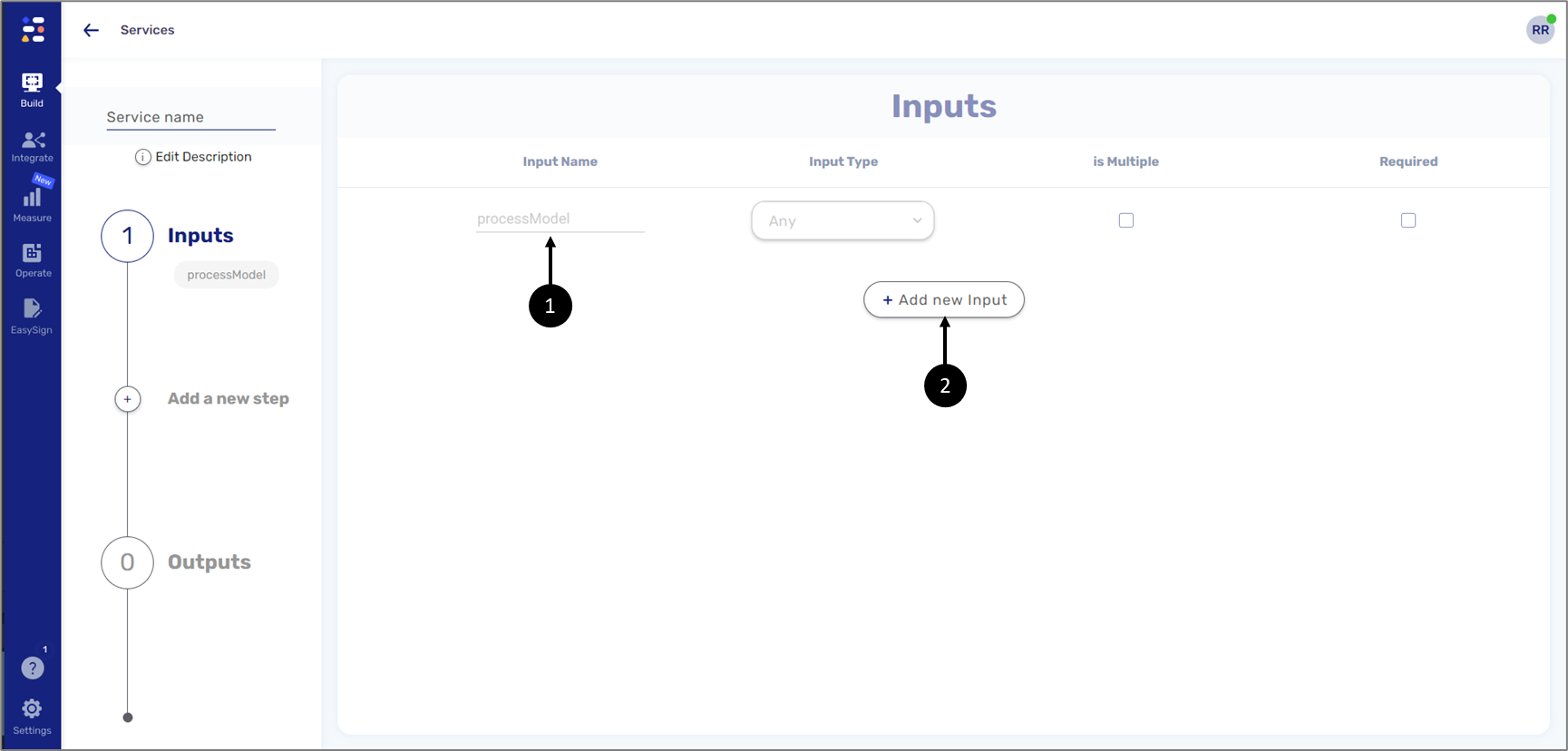
Figure 15: processModel and + Add New Input Button
For the file storage integration, we need to add input for files. We have two methods we can use:
- Add a static number of file inputs - this method will be used when there is a fixed number of files to upload to a storage server.
- Add a file input array - this method offers more flexibility and will be used when the number of files to upload to a storage server is dynamic and may differ
Static Number of File Inputs
(See Figure 16 and Figure 17)
For this method, we will click the + Add new Input button and add the desired number of inputs, for example:
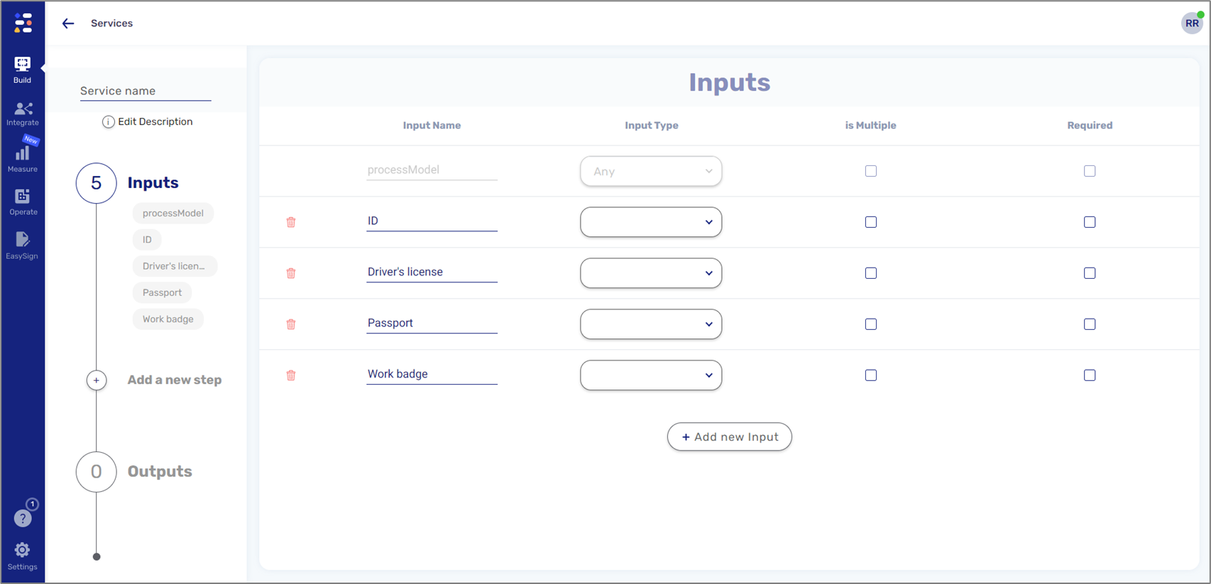
Figure 16: File Inputs
We added four file inputs. To complete, we will set each input type to File, for example:
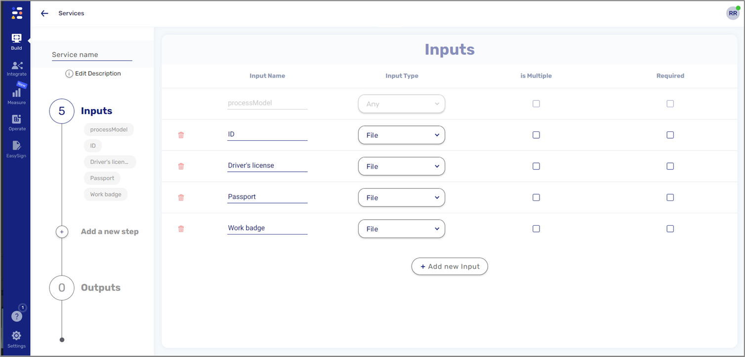
Figure 17: Input Type - File
File Input Array
(See Figure 18 and Figure 19)
For this method, we will add one new input, for example:
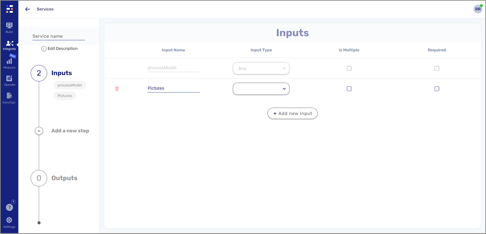
Figure 18: File Input
To complete, we will set the input type to File and check the Is Multiple checkbox (1), for example:
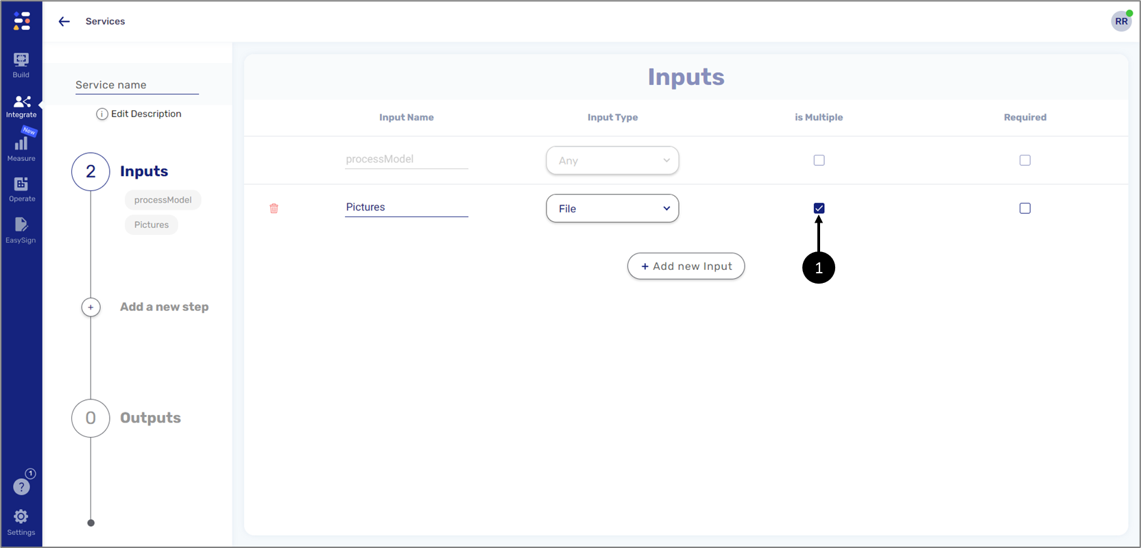
Figure 19: Input Type - File and Is Multiple
Steps
(See Figure 20)
For the file storage integration, the File Storage Service step is required. Other steps such as:
- Code
are optional and will be used only if needed for different scenarios.
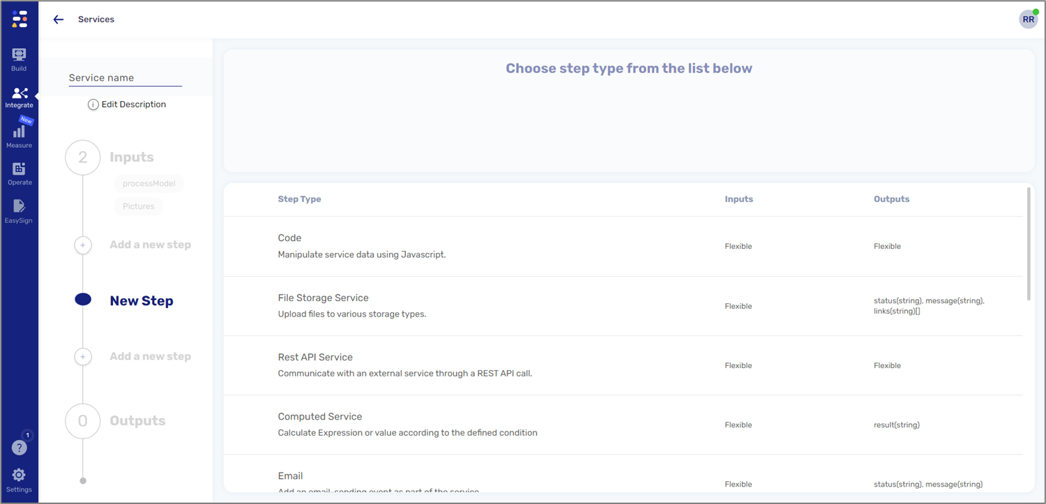
Figure 20: Steps
File Storage Service (Required)
(See Figure 21 to Figure 28)
This step will be used to configure information for file storage.
Before accessing the configuration screen, a name for the step must be provided:
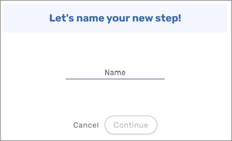
Figure 21: File Storage Service Name
When the File Storage screen appears, we will perform the following actions:
- Use the checkbox (1) to indicate whether we want to use a different file storage resource per environment.
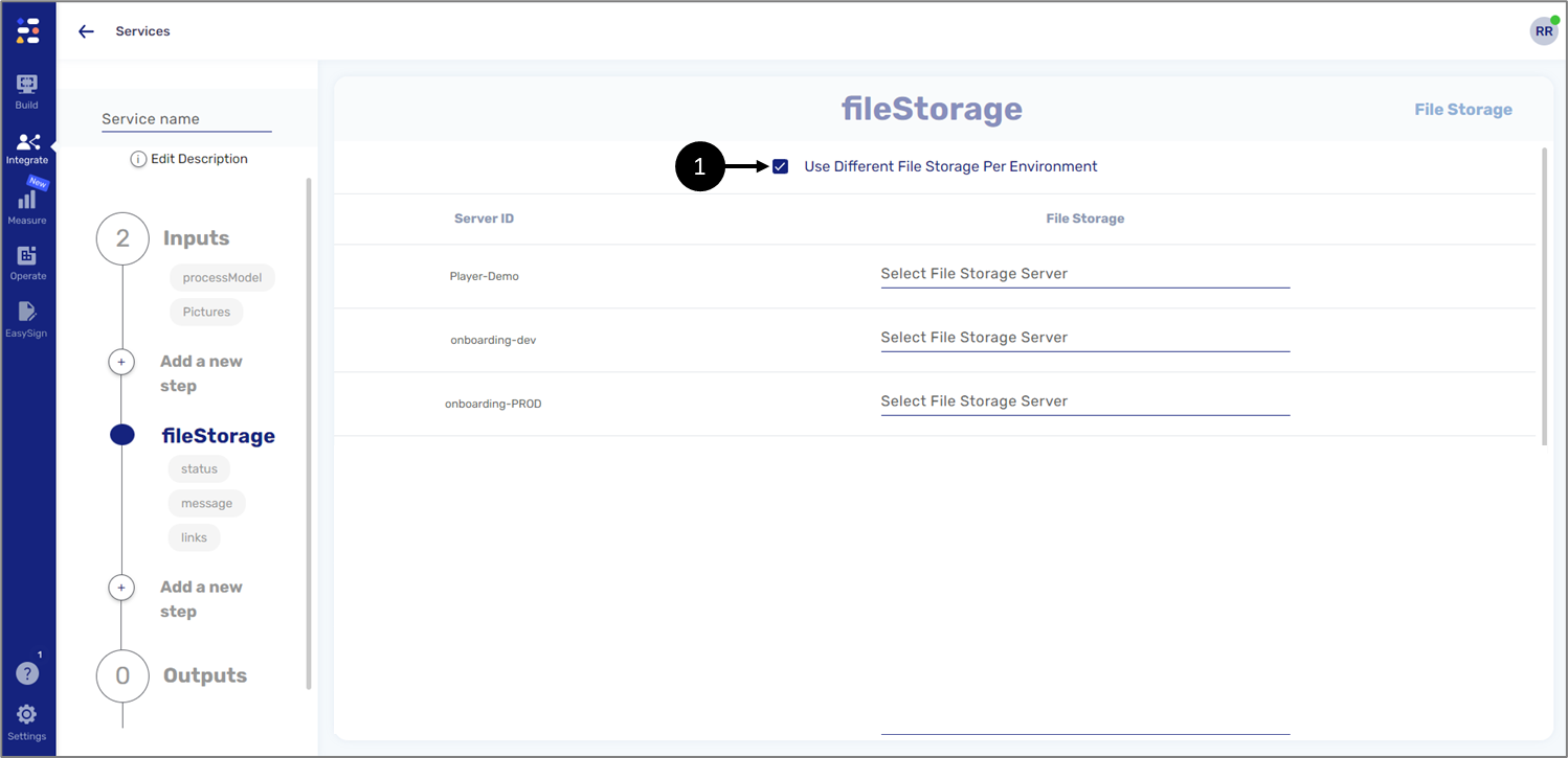
Figure 22: Use Different File Storage Per Environment.
- Add the File Storage Server resource we want to use (2) (the creation of the resource was described in the Creating a File Storage Service Resource section).
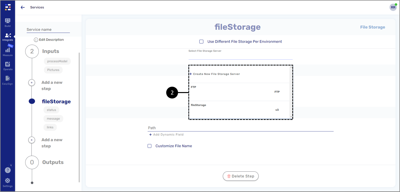
Figure 23: File Storage Service Name

- Add the files to upload (3) - the number of files to add depends on the input method we chose while configuring the Inputs section (for additional information, see the Inputs section):
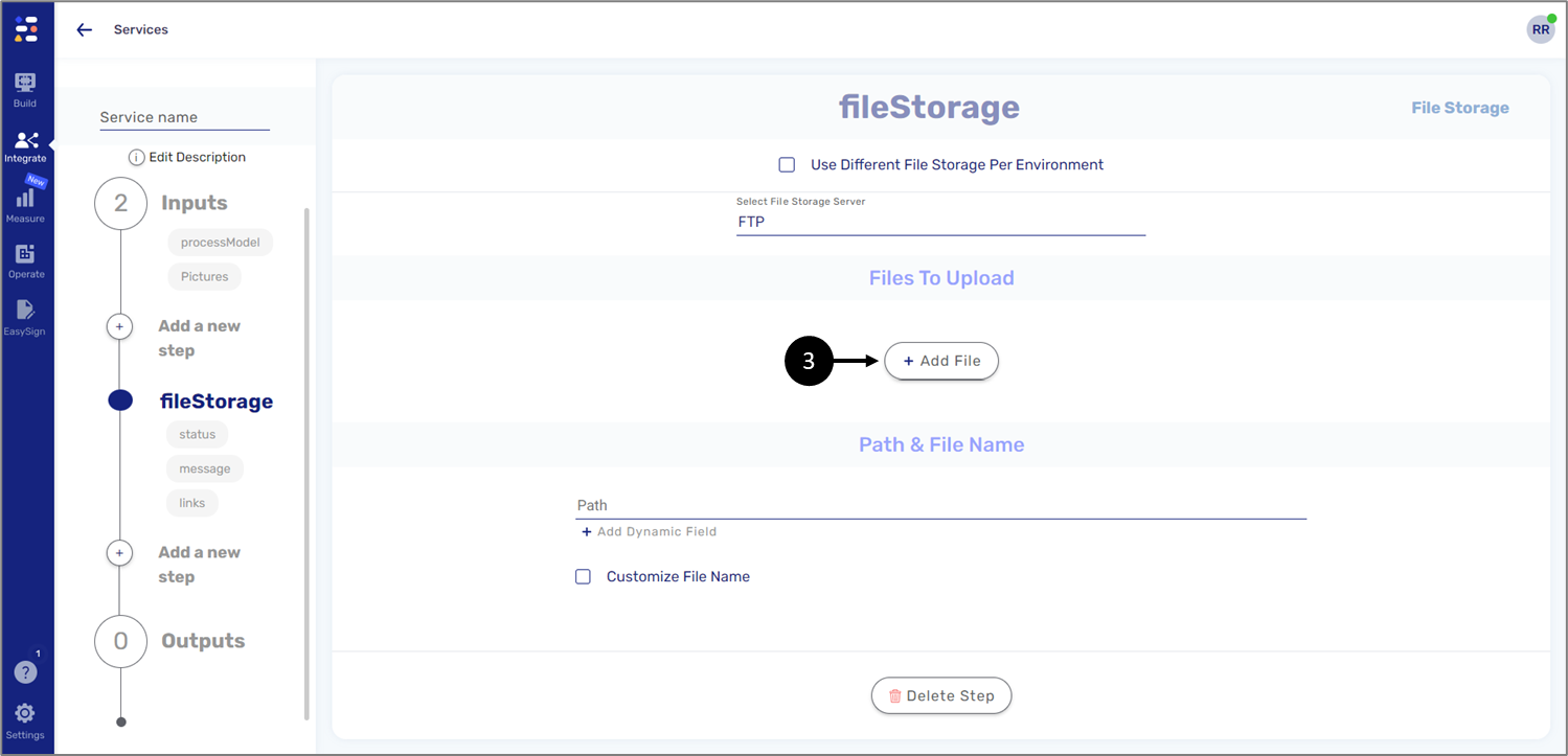
Figure 24: + Add File button
- Static number of file inputs - for this method, we will add files to match the number and names of files that were added in the Inputs section. The files will be added by selecting the Model as the source (4) and by writing the name in the following format: inputs.xxxx (inputs.Passport), for example:
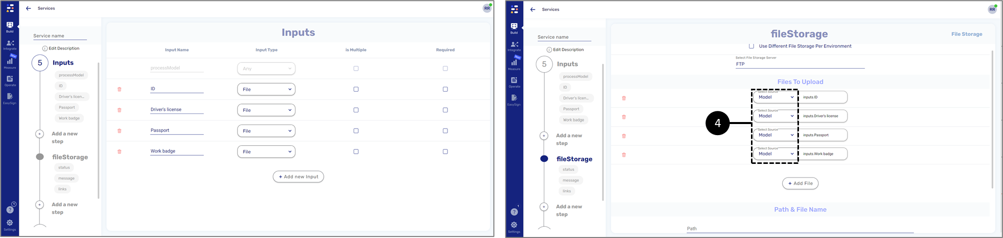
Figure 25: Static Number of File Inputs
- File input array - for this method, we will add one file to match the configuration in the Inputs section. The file will be added by selecting the Model as the source (4) and by writing the name in the following format: inputs.xxxx (inputs.Pictures), for example:
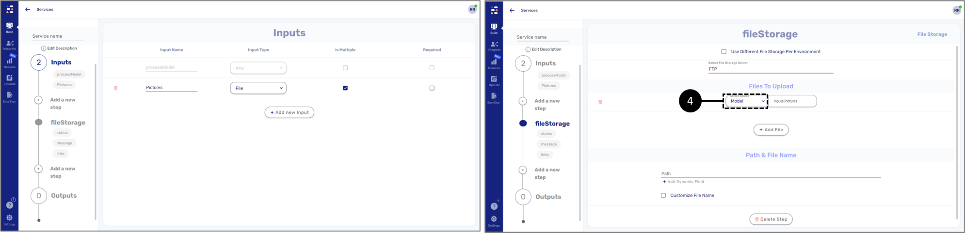
Figure 26: Static Number of File Inputs
- Write the path (5) where the files will be stored. The path can be static or dynamic, for example:
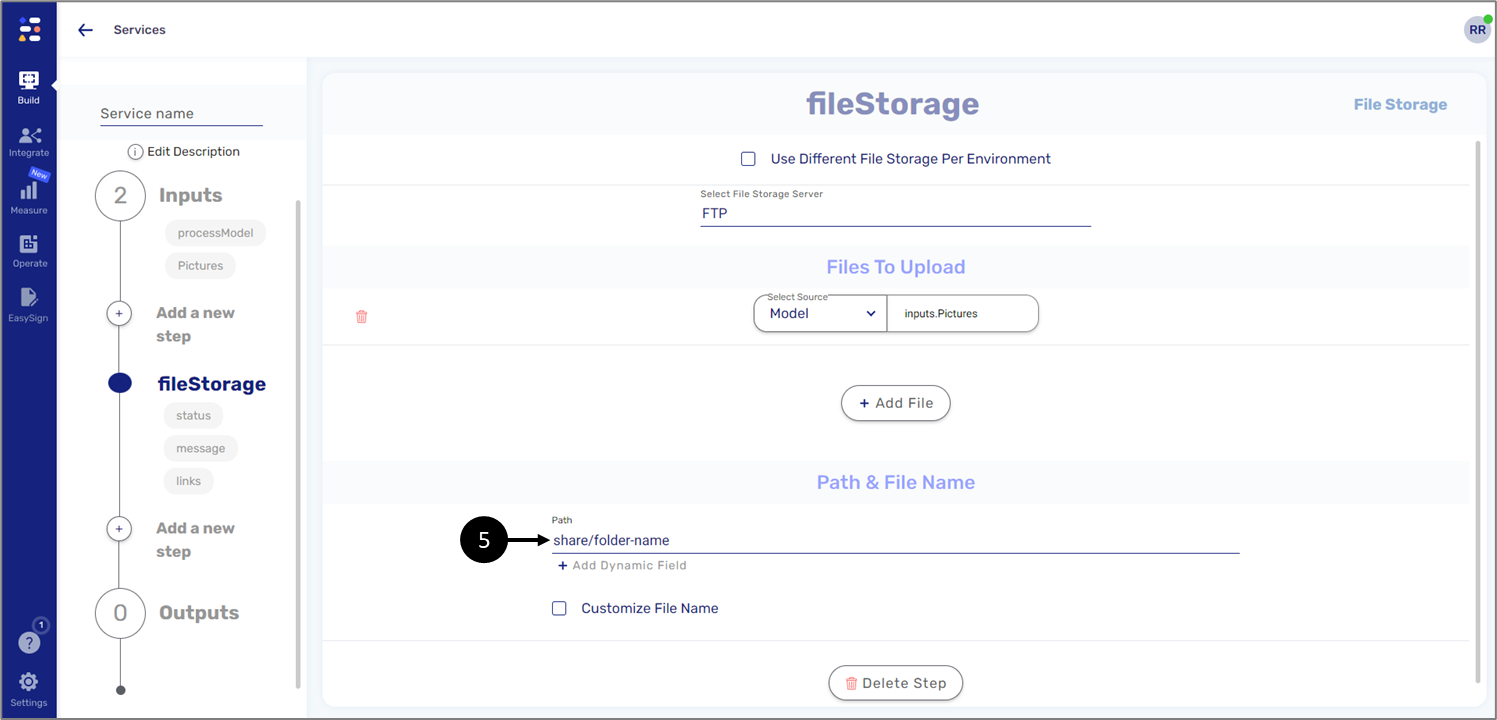
Figure 27: Path
- If required, click the checkbox (6) to customize the file name. For example, we can add a dynamic field with date and time metadata next to the name of the file to create an electronic timestamp (7), indicating when the file was shared to the storage:
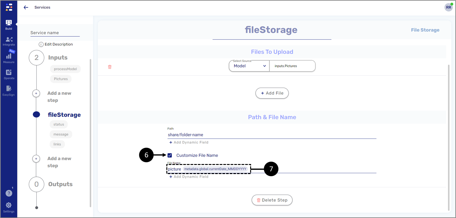
Figure 28: Customize File Name with a Timestamp
Code (Optional)
(See Figure 29 to Figure 33)
This step will be used to manipulate service data using JavaScript. It contains three sections:
- Code - using JavaScript code
- Inputs - creating inputs
- Outputs - creating outputs
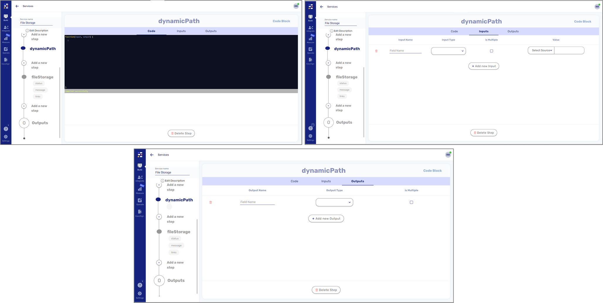
Figure 29: Code Step Structure
For example, we can configure a dynamic path according to a selected environment server (DEV or PROD). First, we will add a String type input variable (1) and set the Value (2):
- Source - Metadata
- Value - transaction.environment
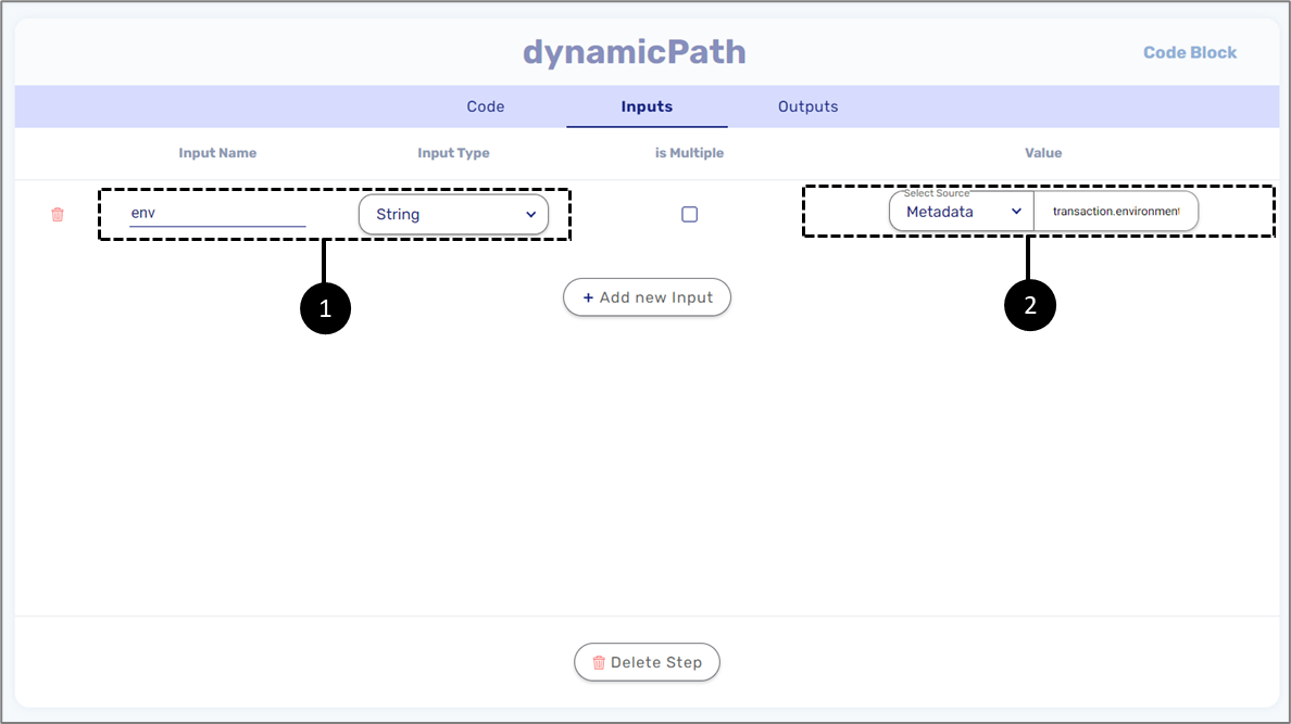
Figure 30: Inputs
Next, we will add a String type output variable (3).
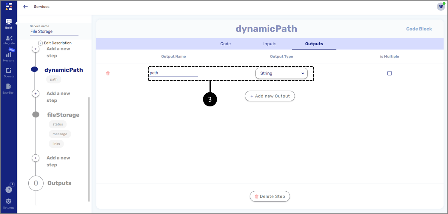
Figure 31: Outputs
Finally, we will write the code utilizing the input and output variables.
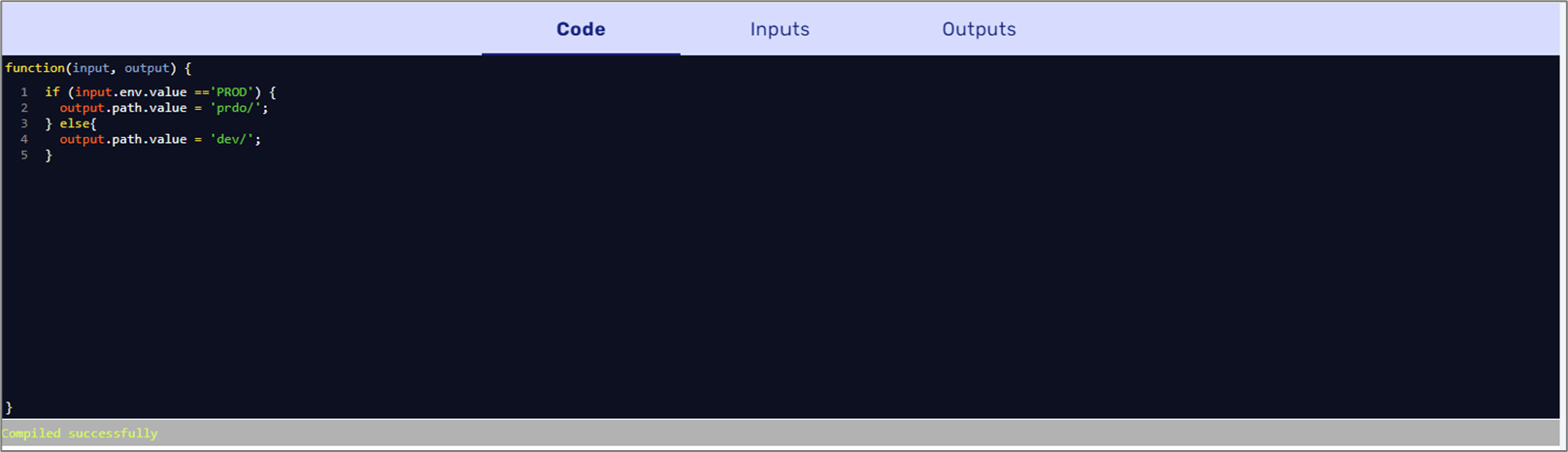
Figure 32: Code
On the File Storage Service step, we will add a new dynamic field and add the Code step output (4).
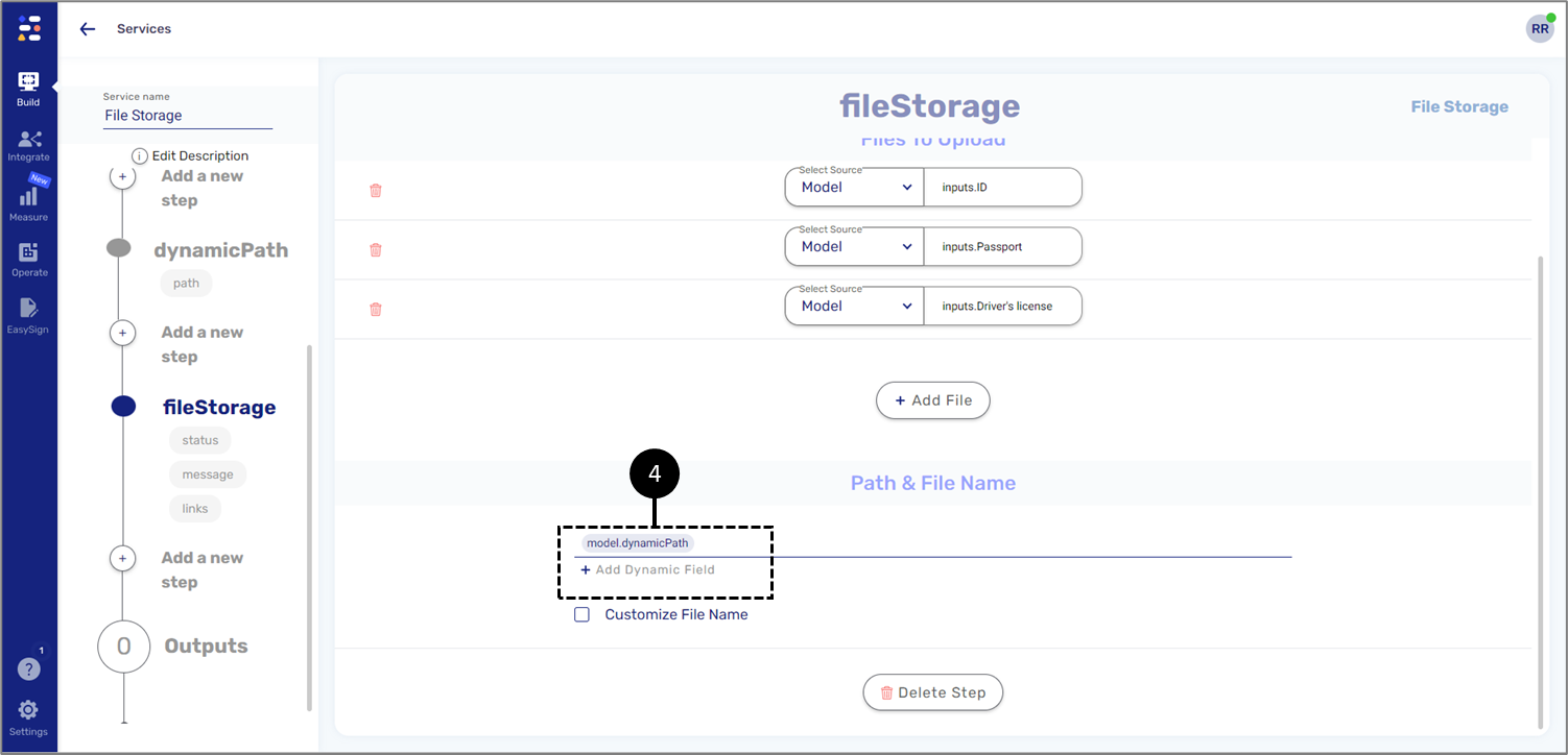
Figure 33: Dynamic Path
Email (Optional)
(See Figure 34)
This step will be used to send an email to static/dynamic recipients. This step must be added after the File Storage Service step.
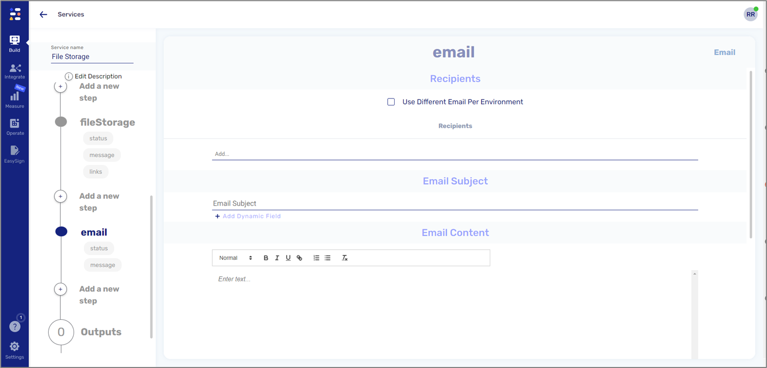
Figure 34: Emil Step Structure
File Storage Integration - Model Structure
(See Figure 34 and Figure 35)
The structure of the Model must match the configuration of the Inputs section. For example:
- If the Inputs section contains multiple file inputs, the Model must contain the same number of file-type data items:
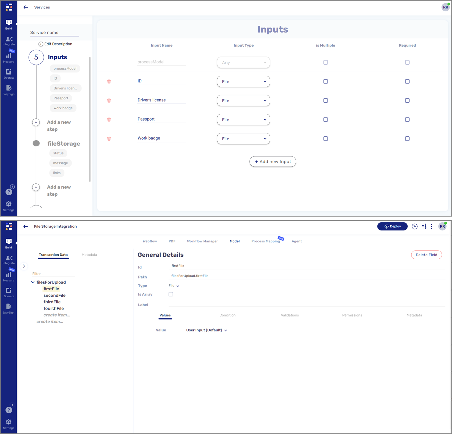
Figure 34: Model Structure - Multiple File Type Data Items
- If the Inputs section contains an array of file inputs, the Model must also contain a file type array:
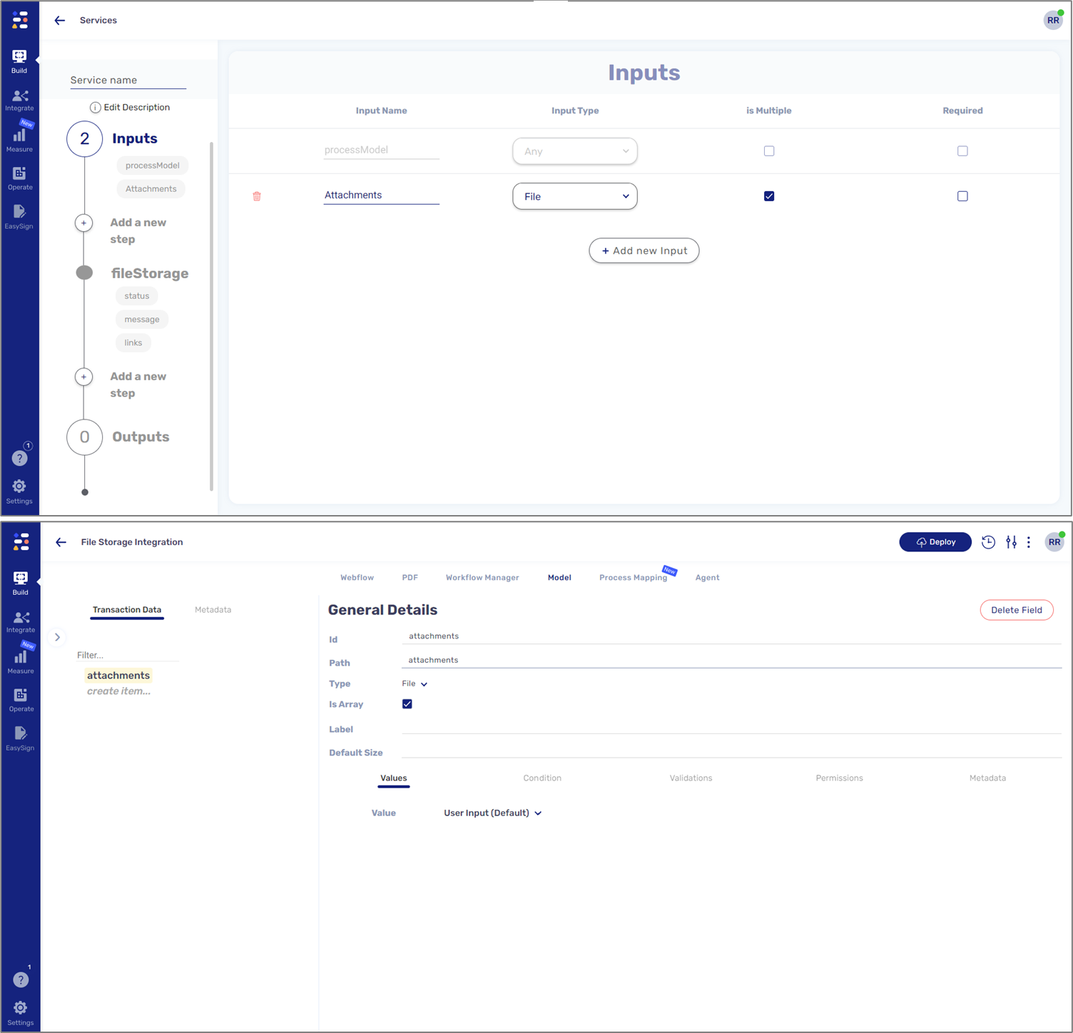
Figure 35: Model Structure - File Type Array
File Storage Integration - Workflow Steps
(See Figure 36 to Figure 39)
To initiate the integration, we must add it as a Workflow step by clicking + Add New Step (1) and Integration (2).
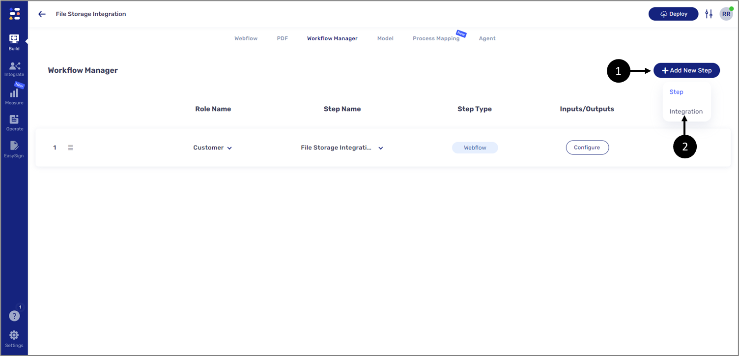
Figure 36: Adding Integration Step
When the Service Lookup window appears, we will select the desired file storage integration (3) and click OK (4).

Figure 37: Service Lookup Window
After selecting the integration, we will specify the input according to the structure of the Model (5) and click OK (6). For example:
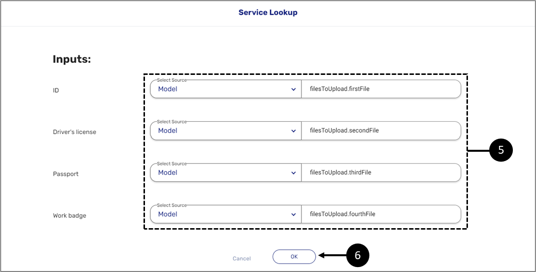
Figure 38: Adding Inputs
The Integration step is now configured (7).
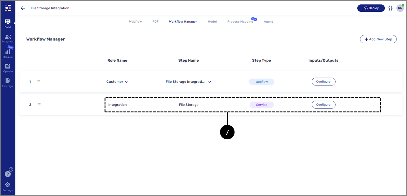
Figure 39: Add Integration Step
Usage Example
The following sections describe an end-to-end usage example of a file storage integration.
Step 1: Creating File Storage Server Resource
(See Figure 40)
In the first step, we will access the Service screen and create the File Storage Server resource according to the instructions described in the Creating a File Storage Server Resource section.
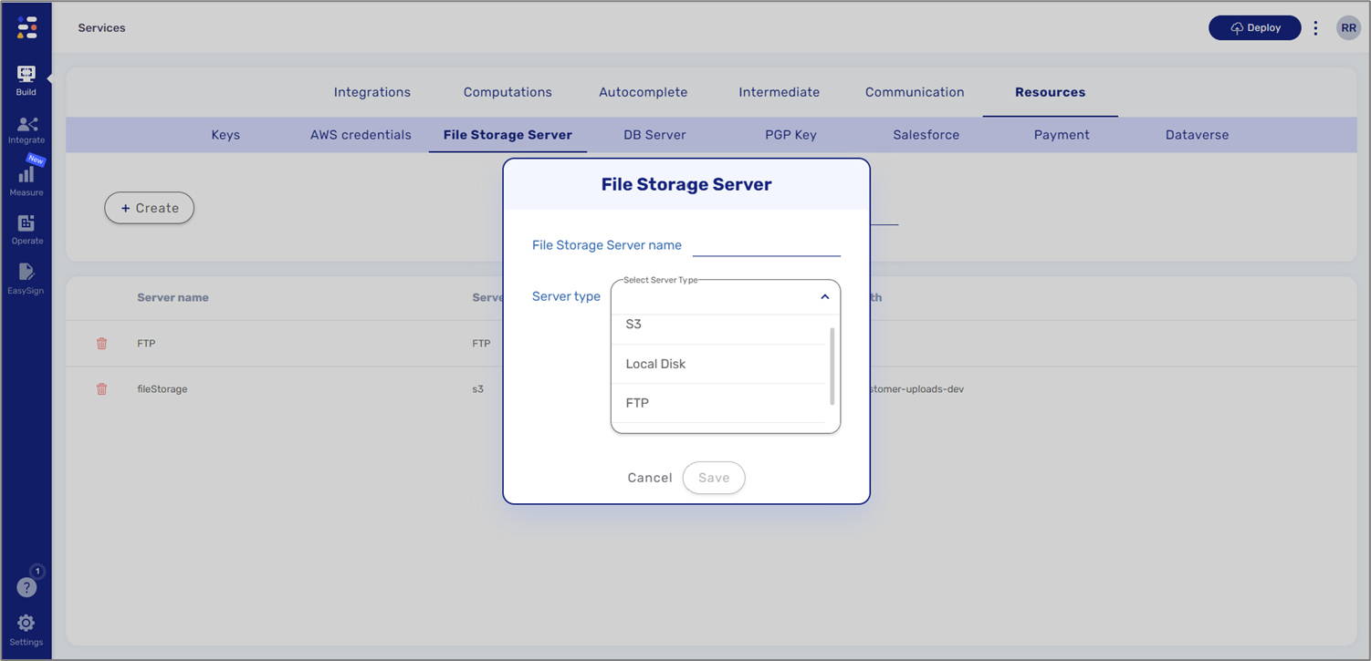
Figure 40: Creating File Storage Server Resource
Step 2: Creating a New Integration
(See Figure 41)
In the second step, we will create a new integration and provide a name for it as described in the Creating an Integration section.
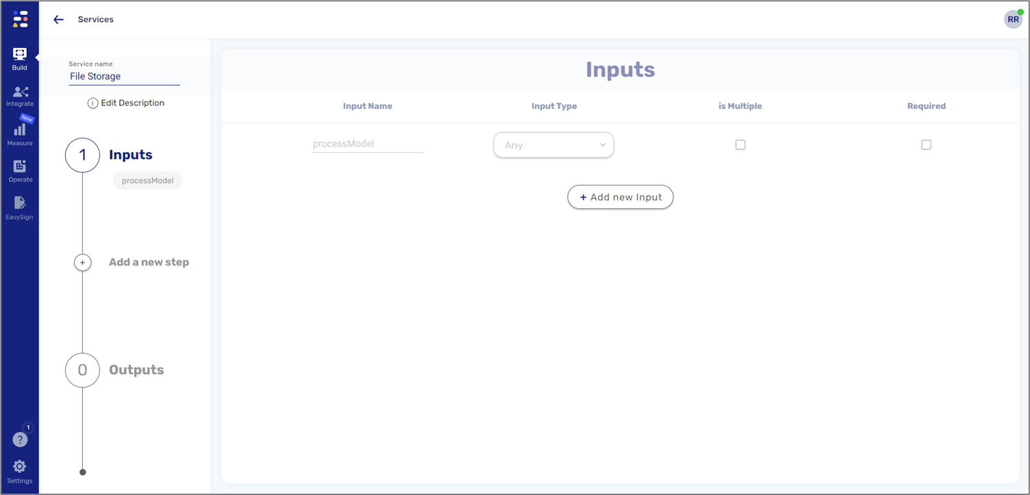
Figure 41: Creating a New Integration
Step 3: Configuring the Integration - Inputs
(See Figure 42)
In the third step, we will configure the Inputs section according to one of the two methods described in the Inputs section.
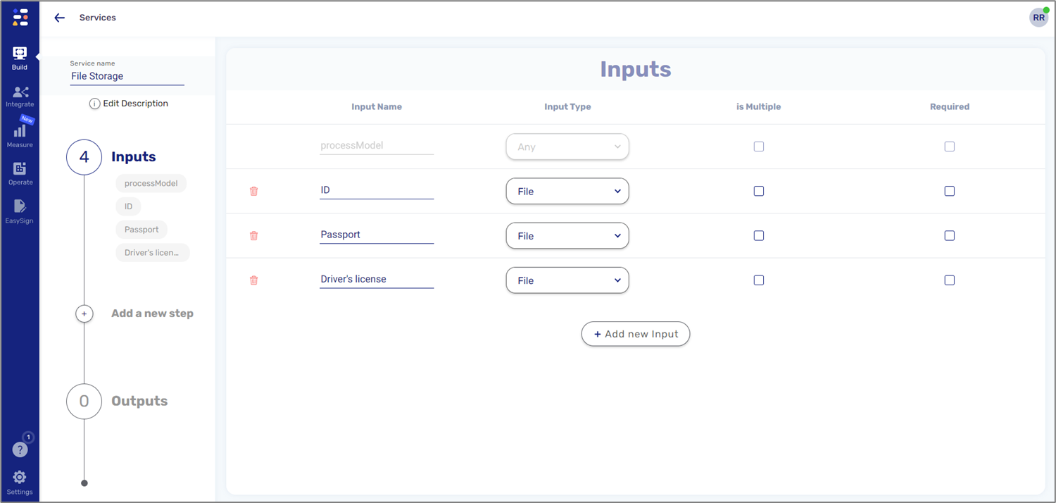
Figure 42: Inputs Section
Step 4: Configuring the Integration - Steps
(See Figure 43)
In the fourth step, we will add the required File Storage Service step and configure it as described in the Steps section.
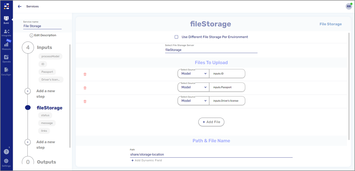
Figure 43: File Storage Service Step
Step 5: Deploying the Integration
(See Figure 44)
In the fifth step, we will click the checkbox of the Integration we created (1), click the Deploy button (2), and select the desired environment (3).
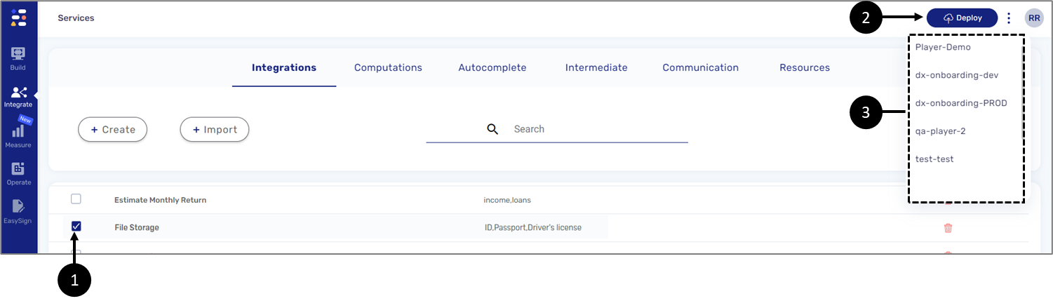
Figure 44: Deploying the Integration
Step 6: Building the Webflow and Model
(See Figure 45 and Figure 46)
In the fifth step, we will build the Webflow and the Model. The structure of the Webflow and the Model is dynamic and changes according to the purpose of the digital process. For the Webflow, we must make sure it contains components for uploading files.
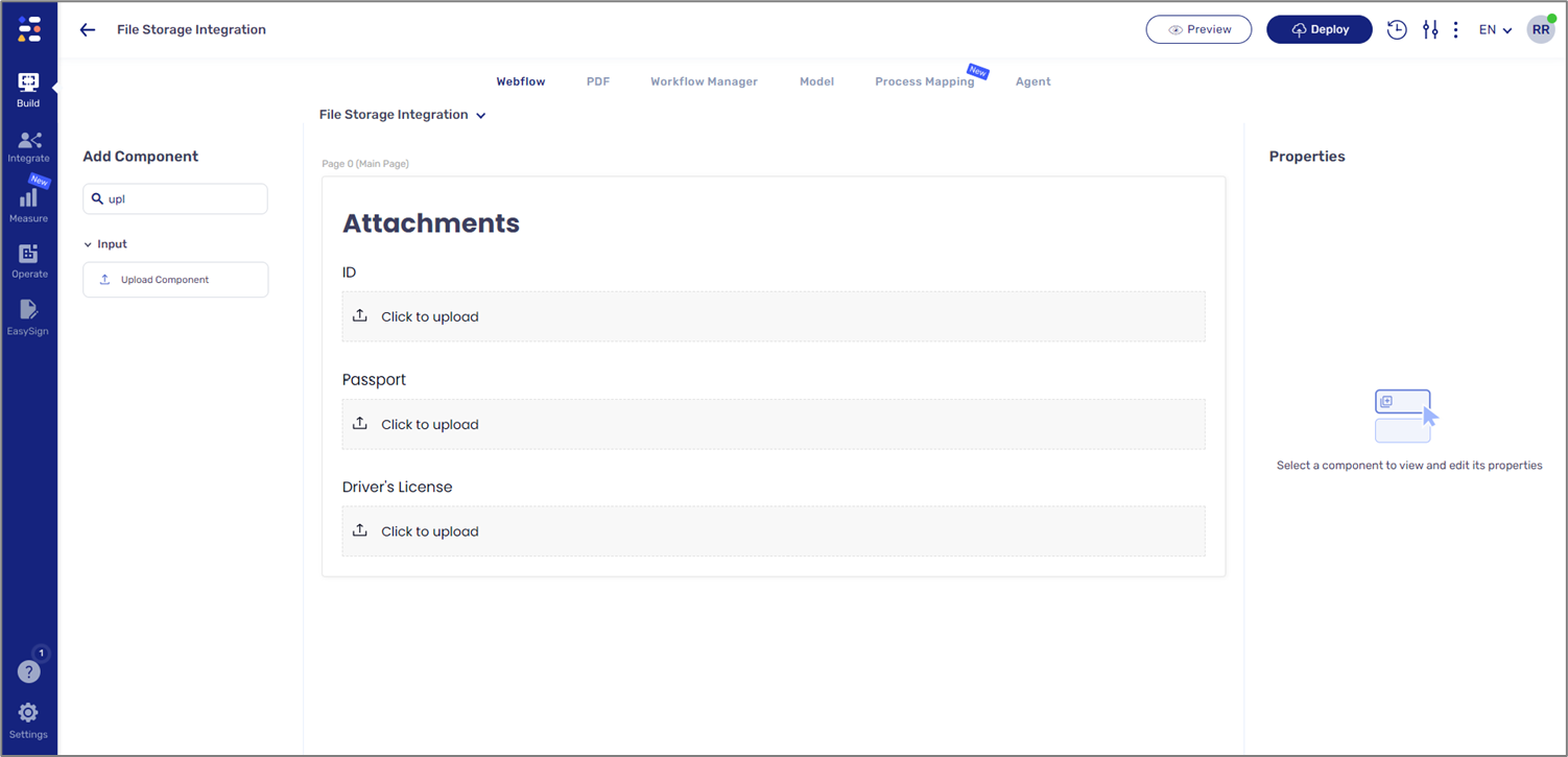
Figure 45: Webflow Structure
The Model must contain data items to match the configuration of the Inputs section. For additional information, see the Model Structure section.
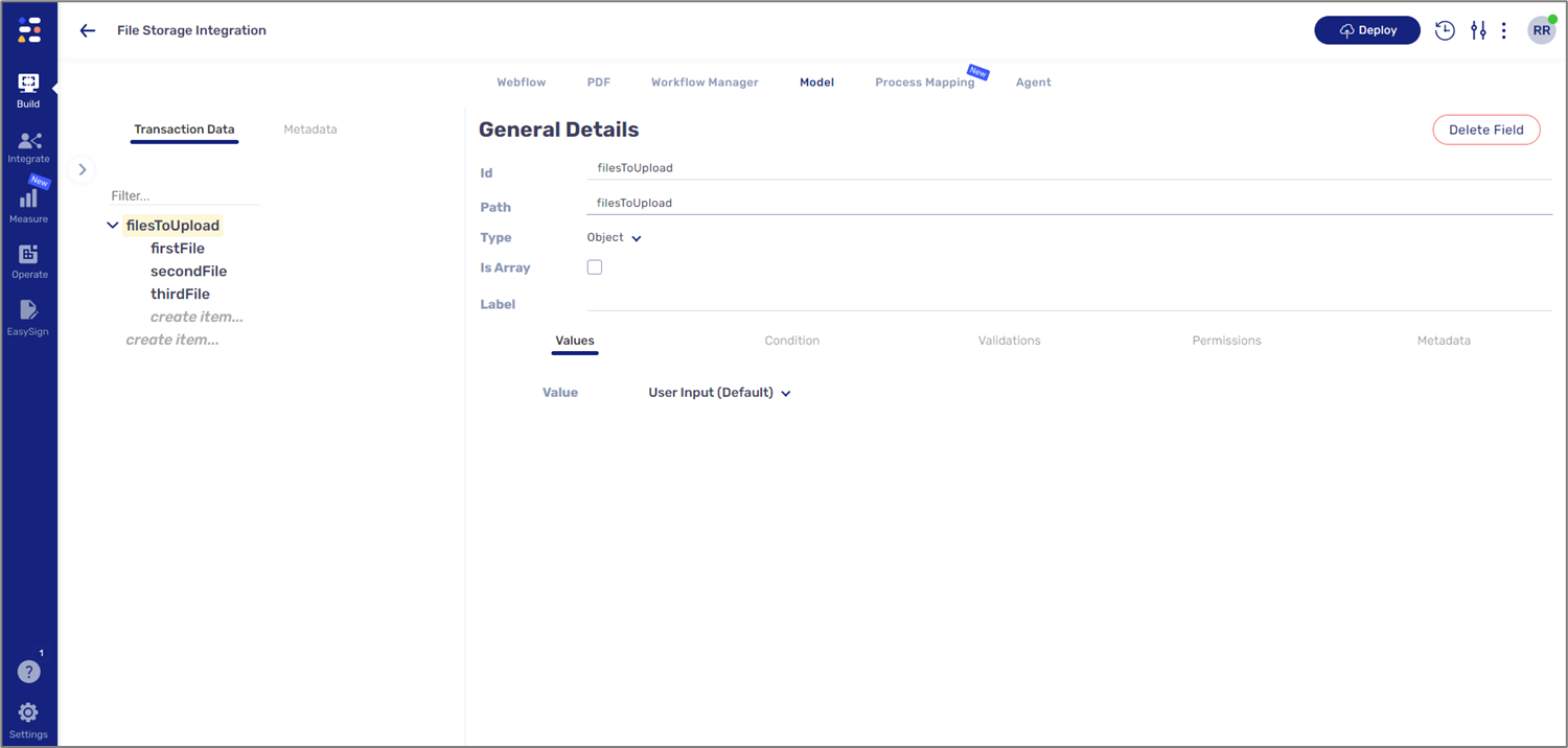
Figure 46: Model Structure
Step 7: Configuring the Workflow Manager
(See Figure 47)
In the sixth step, we will add an Integration step as described in the Workflow Steps section.
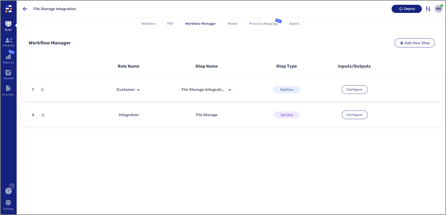
Figure 47: Added Integration Step